1.Description:
XY-PWM signal generator is a device that provides electrical signals at a variety of frequencies, square wave, and output levels.It is used as a signal source or excitation source for testing.Widely used in production practice and technology.
2.Features:
1>.With outer casing;
2>.LCD high definition display;
3>.Support UART;
4>.Support frequency adjustment;
5>.Support duty cycle adjustment;
6>.High precision detection;
7>.Support power-down memory function;
8>.1-Channel PWM output.
3.Parameters:
1>.Product name: PWM Signal Generator;
2>.Model: XY-PWM;
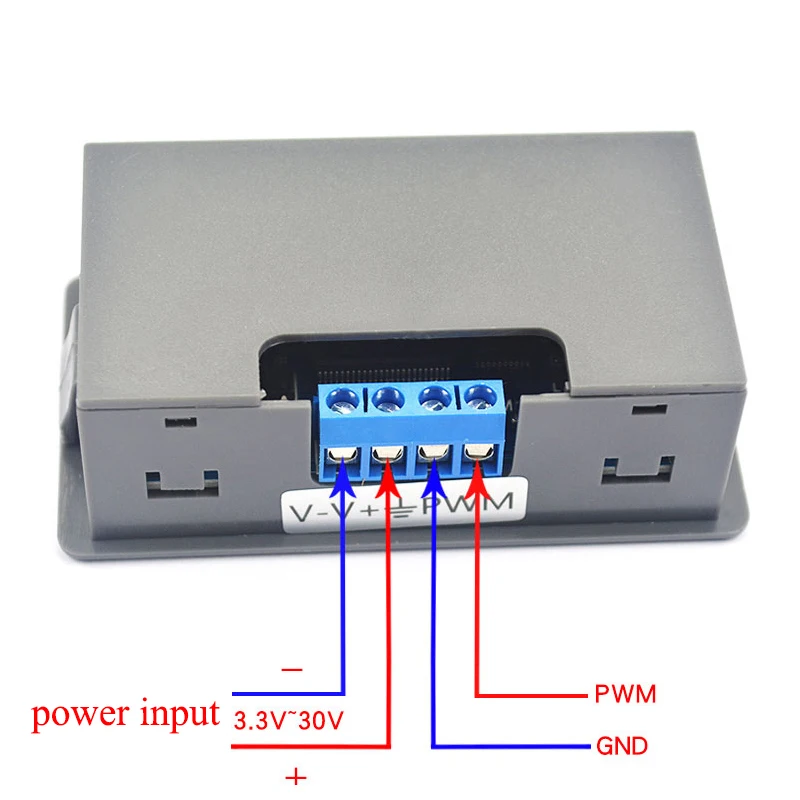
3>.Work voltage:DC 3.3V-30V;
4>.Frequency range:1Hz~150KHz;
5>.Frequency accuracy:2%;
6>.Duty cycle range:0.00%-100%;
7>.Output Current:About 5-30mA;
8>.Output amplitude:Same to input voltage;
9>.Size:79*43*27mm;
10>.Operating temperature:-20℃~70℃;
4.Frequency set range:
Enter the settings interface when short press any button ‘FREQ+’ or ‘FREQ-’ in the normal running status to select frequency range.Automatically switch frequency range.
Pay attention to the position where the decimal point moves when the button is pressed.
Display ‘XXX’.No decimal point,The minimum frequency is 1Hz.The frequency range is 1Hz ~ 999Hz.
Display ‘X.XX’.The decimal point is the penultimate, The minimum frequency is 0.01KHz.The frequency range is 1.00KHz ~ 9.99KHz.
Display ‘XX.X’.The decimal point is the third last,The minimum frequency is 0.1KHz.The frequency range is 10.0KHz ~ 99.9KHz.
Display ‘X.X.X’.The decimal point is fully lit,The minimum frequency is 1KHz.The frequency range is 1KHz ~ 150KHz.
For example:
Display ‘100’ means PWM output frequency is 100Hz;
Display ‘1.01’ means PWM output frequency is 1.01KHz;
Display ‘54.1’ means PWM output frequency is 54.1KHz;
Display ‘1.2.4’ means PWM output frequency is 124KHz;
5.Duty cycle set range:
Enter the settings interface when short press any button ‘DUTY+’ or ‘DUTY-’ in the normal running status to select duty cycle.Automatically switch frequency range.
Duty cycle range is 0.00%-100%.
6.Use steps:
1>.Connect to power supply;
2>.Short or long press button ‘FREQ+’ or ‘FREQ-’ to set frequency;
3>.Short or long press button ‘DUTY+’ or ‘DUTY-’ to set duty cycle;
4>.Connect to load.
7.UART communication and parameter settings
The system supports UART data upload and parameter setting functions (TTL level);
UART: 9600, 8, 1
1>.Set PWM frequency:
‘F101’:Set frequency is 101Hz.‘101’ can by replace by 001~999;
‘F1.05’:Set frequency is 1.05KHz.‘1.05’ can by replace by 1.00~9.99;
‘F10.5’:Set frequency is 10.5KHz.‘10.5’ can by replace by 10.0~99.9;
‘F1.0.5’:Set frequency is 105KHz.‘1.0.5’ can by replace by 1.0.0~1.5.0;
2>.Set PWM duty cycle:
‘DXXX’:Set duty cycle is XXX. ‘XXX’ can be 000-100.
E.g:‘D051’ means PWN duty cycle is be set as 51%.
3>.Read set parameter:
Send ‘read’ and then get parameter.
4>.Return value:
Return ‘DOWN’:Set success.
Return ‘FALL’:Set fail.
8.Application:
1>.Square wave signal generator, generating square wave signal for experimental development;
2>.Used to generate a square wave signal that controls the motor driver;
3>.Generate adjustable pulses for use by the MCU;
4>.Dimmer;
5>.Speed governor;
9.Note:
1>.It`s 1-channel PWM output signals are the same.They can not adjust independently.
10.Package:
1>.1pcs XY-PWM PWM Signal Generator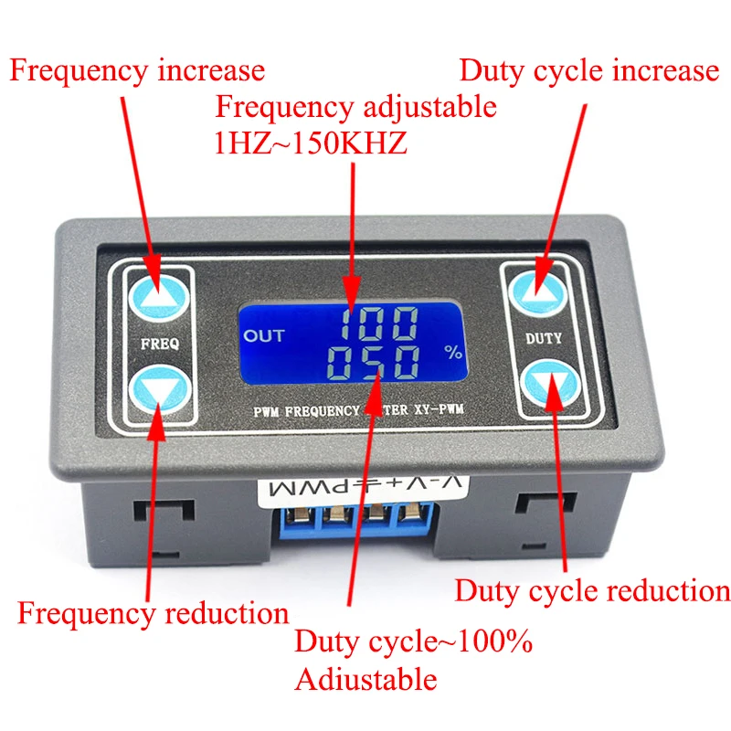


 배송기간
배송기간


