|
|
     aHR0cDovL2ZyZWVzaGlwLmNvLmty aHR0cDovL2ZyZWVzaGlwLmNvLmty
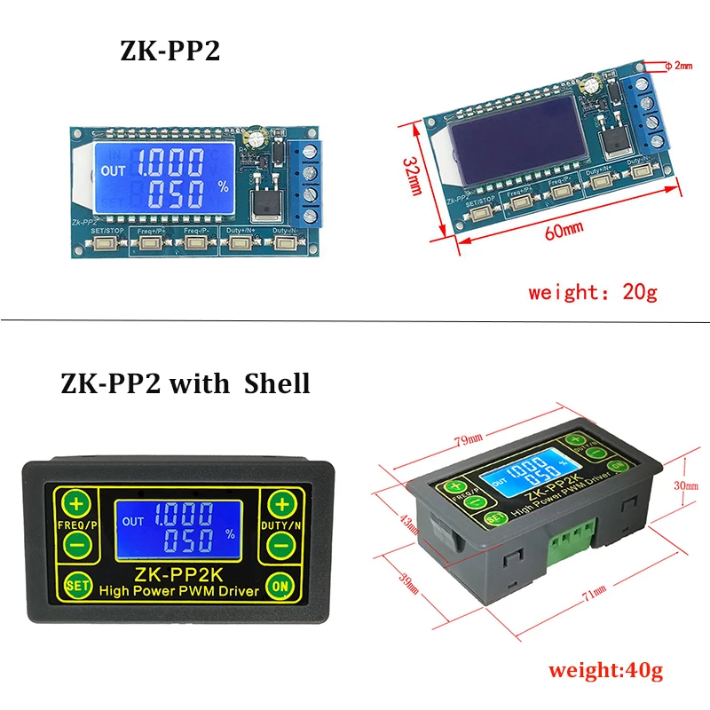
- 모델 번호: ZK-PP2
- DIY 용품: ELECTRICAL
- 브랜드 이름: MAXGEEK
- 원산지: 중국
- S: 64032 64040
옵션정보[(200025551)without shell] [(366103)with shell] [(366103)with shell]
Maxgeek High Power PWM Generator and Pulse Generator Driver Frequency Duty Cycle delay Adjustable PWM Driver
PWM Generator & Pulse Generator Frequency Duty Cycle Adjustable PWM Driver
Applications:
1. Adjust LED brightness, frequency and duty cycle.
2. Adjust motor speed, frequency and duty cycle.
3. Drive solenoid valve to close and release. Automatic loop, delay output, number of loops (or infinite loop) can be set.
4. Turn on and off control equipment, do switch fatigue test, voltage drop and other tests to verify the reliability of customer equipment.
5. Delay start load, delay time can be set. Always on or intermittent work after the delay.
Features:
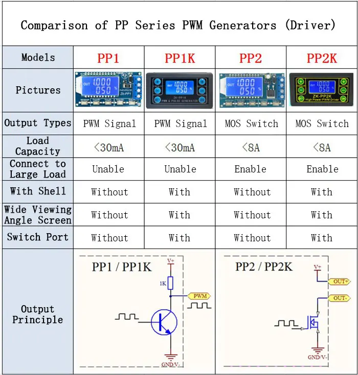
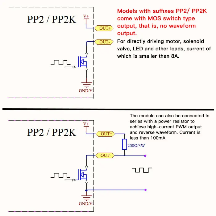
- Can directly drive LEDs, motors, solenoids and other loads.
- Two modes can be selected: PWM mode: frequency (continuous), duty cycle. Attention: The number of pulses cannot be set in this mode, the module will always send pulses. PULSE mode: positive pulse width time, negative pulse width time, power-on delay start time, and switching times are adjustable.
- With start and stop button to control the output and stop of signals.
- Wide voltage input 3.3-30V, with 5.08mm wiring terminal.
Technical Parameters:
- Working voltage: 3.3~30V (Reverse connection is not allowed)
- Frequency range: 1Hz~150KHz, accuracy about 2%. Motor speed is generally selected 20KHZ.
- Duty cycle range: 0-100%, 1% stepping
- Number of pulses: 1-9999, or infinite (---- displayed stands for infinity)
- Delay output time: 0.000s-9999s. The minimum can be set 1ms
- Positive and negative pulse width length: 0.000s-9999s. The minimum can be set 1ms
- Signal loading capacity: less than 8A (MOS switch tube)
- Output amplitude: amplitude is equal to supply voltage (OUT+ is directly connected to V+ inside the module)
Package including
- 1 x PWM Pulse Generator
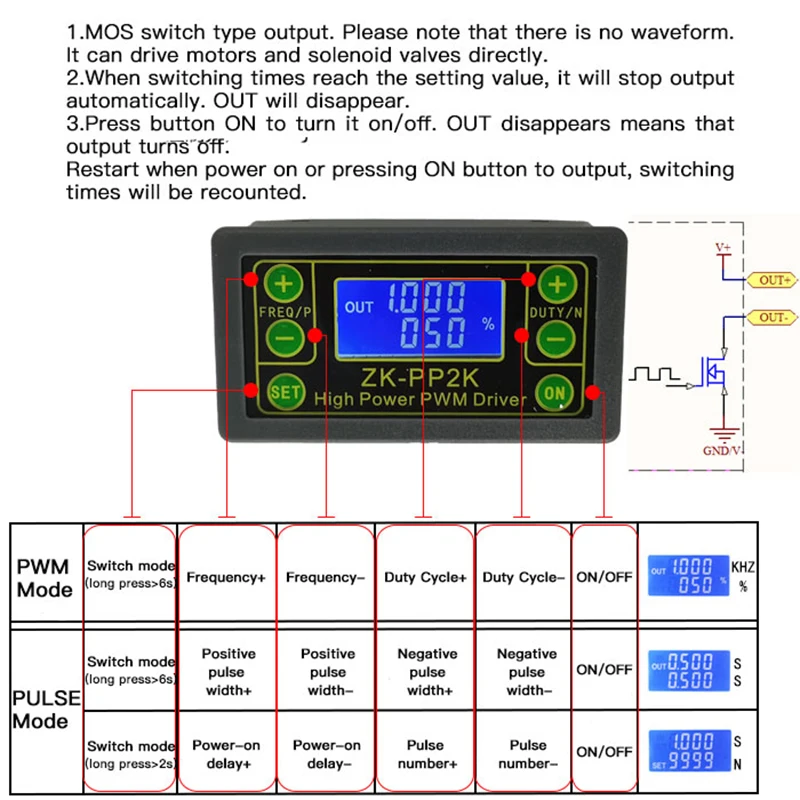
1.Button Operation Instructions
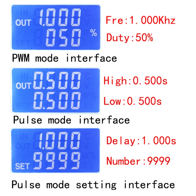
2.PWM Mode (display with % for PWM mode)
Default mode is PWM mode. Set frequency through buttons FREQ+ and FREQ-. Set duty cycle via buttons DUTY+ and DUTY-. Short press button STOP to control signals` output or stop. Output is 0 when stopped. When OUT is displayed on the screen, the module has output. Otherwise, the output is stopped. Default frequency is 1KHZ and duty cycle is 50%.
If you need to switch to PULSE mode, press and hold button SET (more than 6 seconds). Do not release it, you will see the screen change and % disappear. Now the module is in PULSE mode.
PULSE Mode (No % on the right side of the display is PULSE mode)
By buttons P + and P-, you can set positive pulse width time which is displayed in the top line in LCD screen. Press N + and N- buttons to set negative pulse width time, which will be displayed in the lower line in LCD screen, with unit in seconds. Short press button STOP to control signal to output or stop. Output is 0 when stopped. The module has output when the screen displays OUT. Otherwise, output is stopped. Default positive pulse width is 0.5 seconds, and negative pulse width is 0.5 seconds.
Setting of pulse number and delay time: In PULSE mode, long press button SET for 2 seconds, then release it to enter pulse number and delay time setting interface. The screen displays SET. After entering the interface, output pulse will be turned off and cleared. Set delay time by pressing buttons P + and P-. Set the number of pulses by pressing buttons N + and N-. Default delay time is 0 seconds and default number of pulses is infinite (display ----). Press and hold SET button for 2 seconds, the module will automatically return to pulse interface. Press button STOP. After delay setting time is completed, the set number of pulses will be sent. After sending the pulse number, the module will output 0 automatically. If the period is not completed, press STOP button to turn off and clear output pulse. The number of pulses set will be sent every time it is started.
4 Application Operation Examples
4.1 PWM output 20KHZ, 60% duty cycle: Select PWM mode, the frequency is set to 20.00, and the duty ratio is set to 060%.
4.2 The output is turned on for 0.6 seconds and turned off for 0.2 seconds. Infinite loop: select PULSE mode, the positive pulse width is set to 0.600, the negative pulse width is set to 0.200, the delay time is set to 0.000, and the number of pulses is set to --- -.
4.3 Power on or press the start button, delay 5 seconds, then the output is turned on for 0.6 seconds, off 0.2 seconds, infinite loop: select PULSE mode, positive pulse width is set to 0.600, negative pulse width is set to 0.200, delay The time is set to 5.000 and the number of pulses is set to ----.
3.4.4 Power on or press the start button, delay 5 seconds, then output high level 10ms low level 10ms pulse 100: select PULSE mode, positive pulse width is set to 0.010, negative pulse width is set to 0.010, delay The time is set to 5.000 and the number of pulses is set to 0100.
4.5 Power-on delay for 10 seconds, then permanently output signal: select PULSE mode, the positive pulse width is set to a number greater than 0, the negative pulse width is set to 0, the delay time is set to 10.00 seconds, and the pulse number is infinite. (----).
4.6 Other applications can explore or consult customer service
Attention: All setup parameters are not lost when it is power-off.
|
|
|
|
|


 배송기간
배송기간


