
 aHR0cDovL2ZyZWVzaGlwLmNvLmty
- DIY 용품: ELECTRICAL
- 브랜드 이름: XMSJ
- 원산지: 중국
Specifications:
I. Overview:
HM350 is a small signal generator, which can generate up to 100KHz frequency and adjustable duty cycle pulse signal; generate steering gear control signal; measure frequency;
The module is easy to use, input frequency data through key operation, and update the output frequency immediately.
2. Product application:
● Signal generator;
● Meter calibration;
● DC motor control;
● measurement frequency;
3. Technical parameter table:
serial numberproject Parameter Unit Remark
1Pulse signal range 1 to 100000 Hz Pulse signal
2Pulse duty cycle range 0—100.0 % duty cycle
3Pulse signal amplitude 5 VDC Maximum amplitude 5.0Vp (the output amplitude remains unchanged)
4Measurement frequency range 1 to 100KHZ
5Measurement frequency resolution 0.01 HZ
6Measuring frequency voltage range ±0.7~10 VDC is directly coupled
7Servo signal frequency 100 Hz
8Servo signal pulse width 500~2500us
9Operating Voltage 7~12VDC
10Working current <50 mA
11size 57*45*20 mm length x width x height
4. Interface description and related operations
P4 interface (power supply)
VDD: Positive power supply (7~12V)
GND: negative power supply
P3 interface
FIN: Measurement frequency input terminal.
P2: The second anti-pulse signal output.
P1: The first positive pulse signal output.
GND: The negative pole of the power supply.
Five, button description
FUN: (select the operation bit of the setting data) or (long press to save the setting parameter function).
UP: Previous page.
DOWN: Next page.
LEFT: Self-add key.
ROGHT: Auto-decrement key.
6. Interface display and operation instructions:
6.1. Set the frequency of the pulse signal
Interface display font:
The first line "1. Frequency "
Second line "*1 1000Hz"
Key operation:
FUN: function key; (select the operation bit of the setting data) or (long press to save the setting parameter function)
LEFT: Self-add key;
ROGHT: self-decrease key;
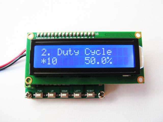
6.2. Set the duty cycle of the pulse signal
Interface display font:
The first line "2. Duty Cycle"
The second line "*0.1 50.0% "
Key operation:
FUN: function key; (select the operation bit of the setting data) or (long press to save the setting parameter function)
LEFT: Self-add key;
ROGHT: self-decrease key;
6.3. Output servo pulse signal
Interface display font:
The first line "3.Servo Control"
The second line "*1 500us"
Key operation:
FUN: function key; (select the operation bit of the setting data) or (long press to save the setting parameter function)
LEFT: Self-add key;
ROGHT: self-decrease key;
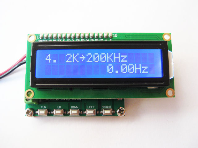
6.4. Measurement frequency
Interface display font:
The first line "4.2K->200KHZ"
Second line "0.00Hz"
Key operation:
Set and change the measurement frequency range key: (LEFT: self-add key)
Running the picture:
set frequency graph

To set the duty cycle map:
Servo signal mode diagram:

frequency meter
Oscilloscope Waveform
Output two channels of positive and negative pulse signal 1kHz

Servo signal 500us


 배송기간
배송기간


