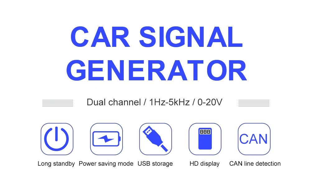
Digital Handheld Signal Generators Jinhan ASG102 free gift Solenoid valve / motor driver Automotive Signal Generator With CAN
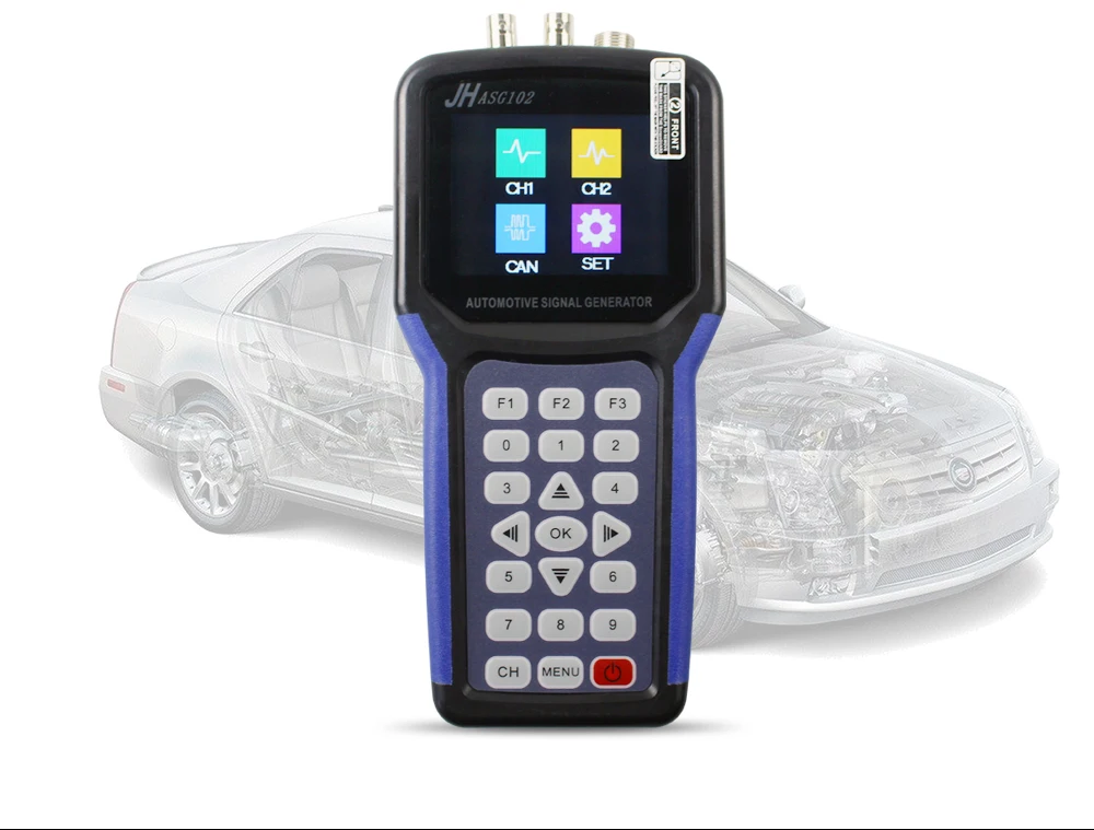
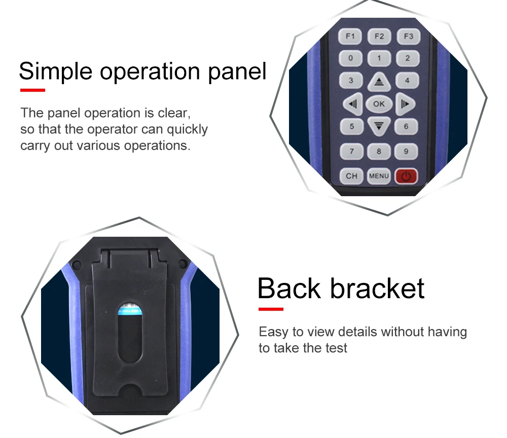
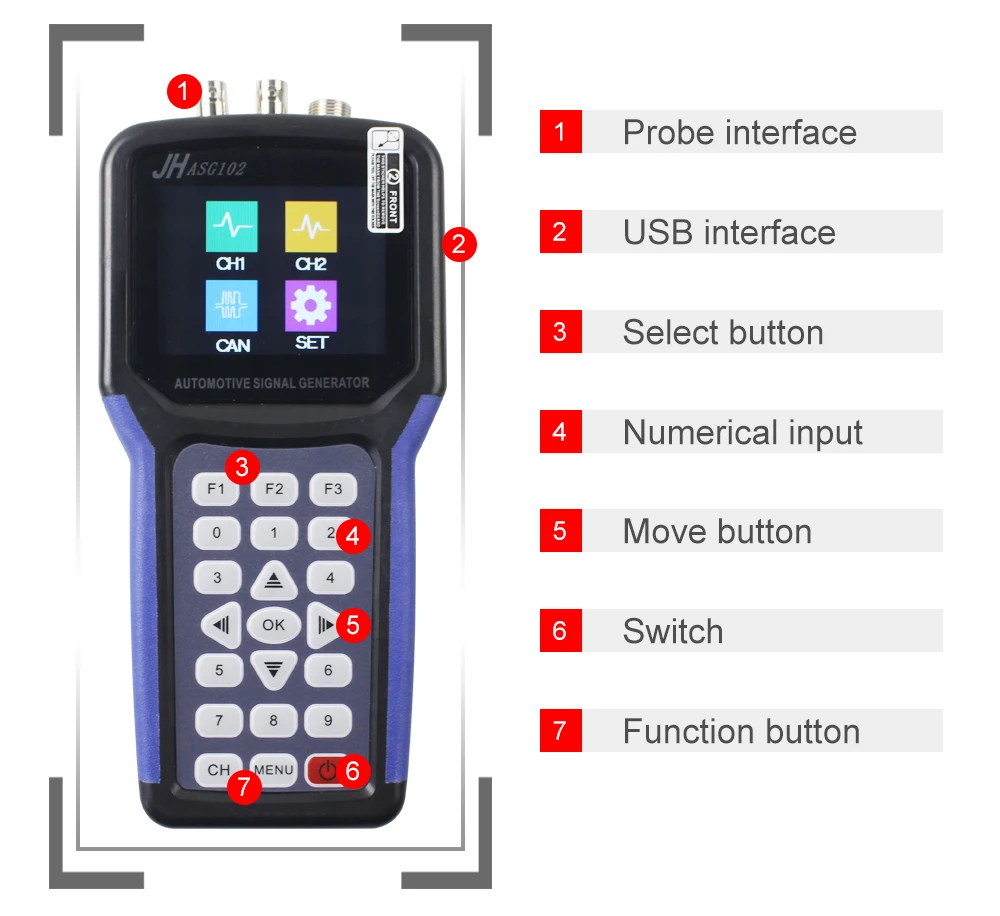
(1) Button description and main functions:
F1: It is mainly used to switch between the first and fourth items.
Or to switch the value of the selected item.
F2: It is mainly used to switch between the 2nd and 5th items, or
to switch the value of the selected item.
F3: It is mainly used to switch between the 3rd and 6th items, or
to switch the value of the selected item.
OK: Determine the button for confirmation or save.
CH : It is mainly used for switching between channel 1 and channel 2
configuration interfaces.
MENU: Mainly used to return to the menu selection interface.
0-9: The number key changes the corresponding digit value to a numeric
key value.
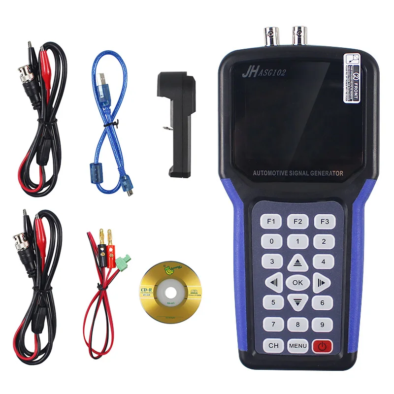
(2) Port description:
CH1: Channel 1 signal output.
CH2: Channel 2 signal output.
CAN: CAN data receiving end.
(3) Instrument features:
According to the automotive rules and actual needs of on-site
diagnosis, the instrument summarizes and analyzes the characteristics of
existing car signal generators:
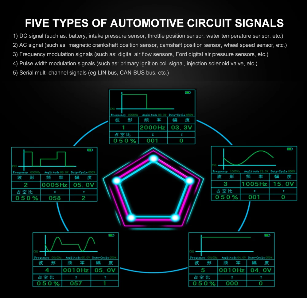
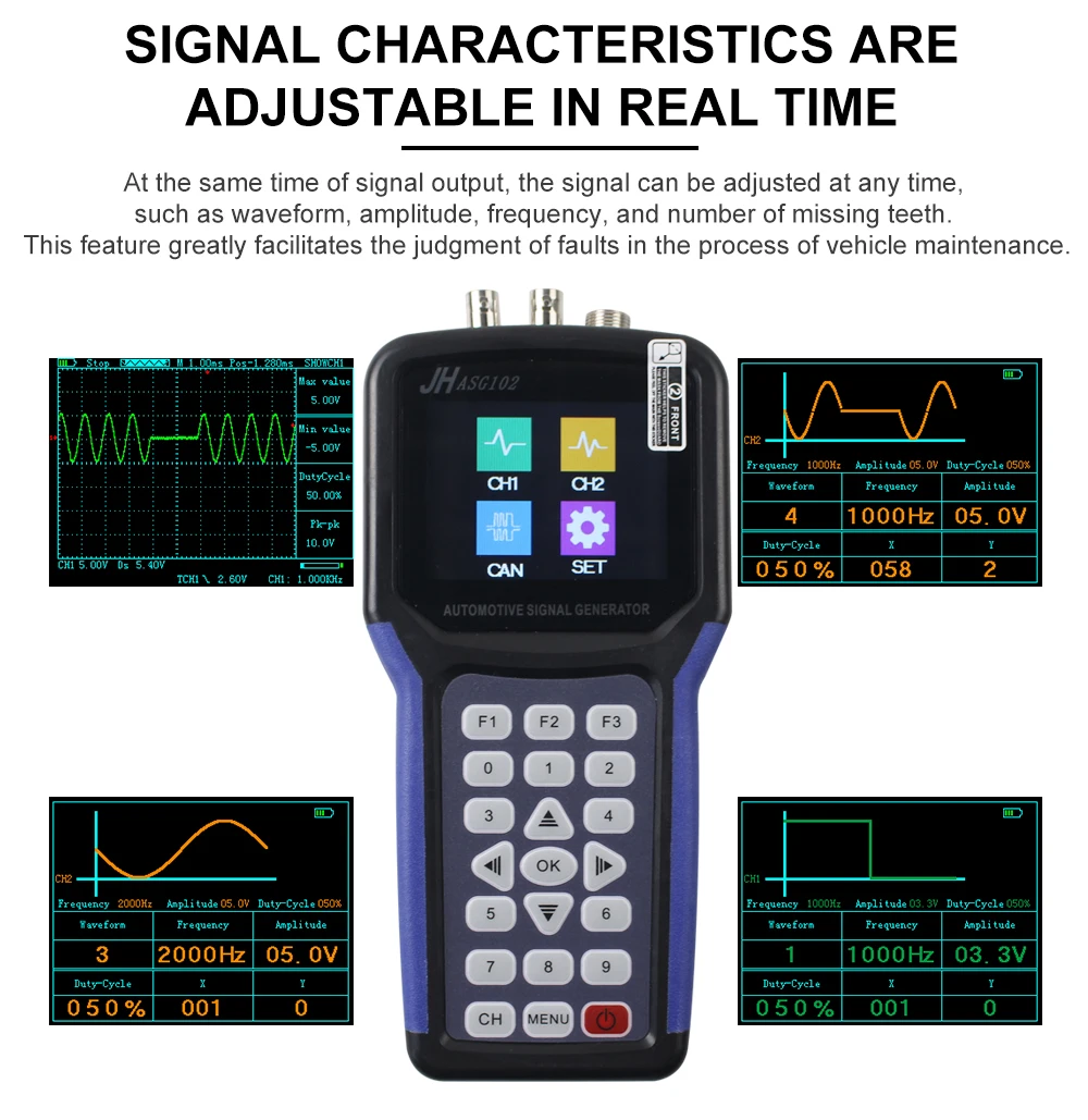
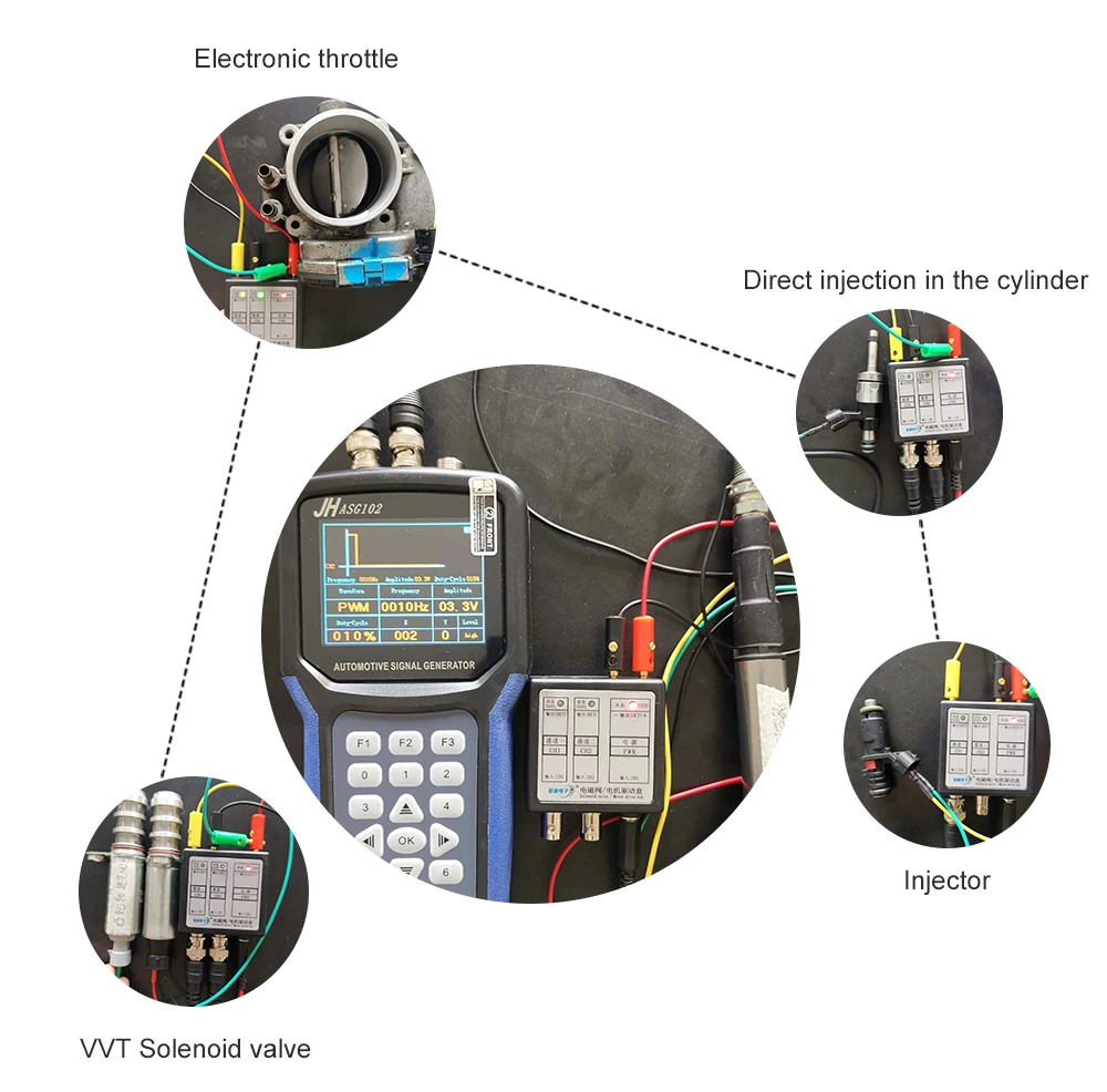
1. The signal characteristics can be adjusted in real time: the signal
can be adjusted at any time by adjust waveform, amplitude, frequency,
missing teeth and other indicators. This feature greatly helps to
determination of the fault in the vehicle maintenance process.
2. Two-channel waveform signal output can simultaneously output signals
of different frequencies, amplitudes and waveforms within two bandwidths.
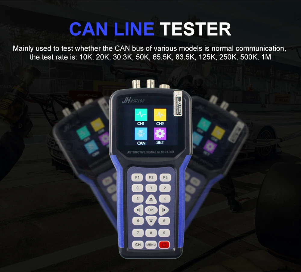
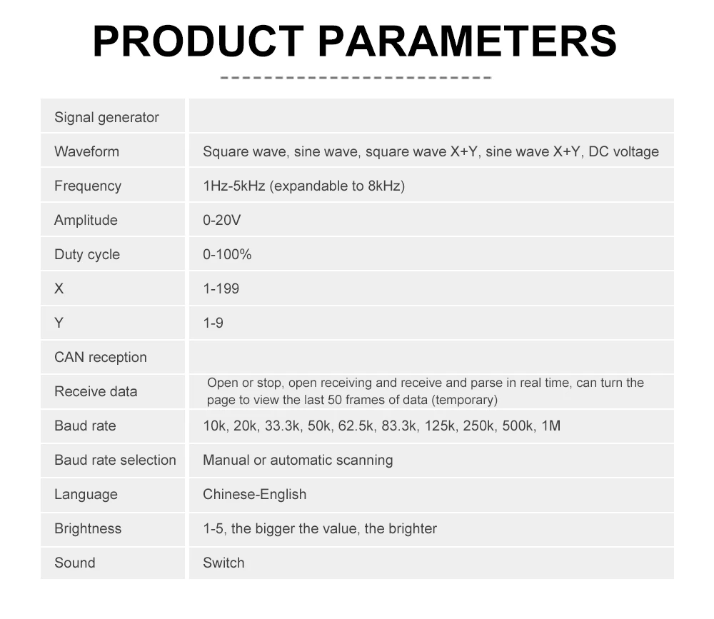
3. CAN bus function:
It is mainly used to test whether the CAN bus of various models is in
normal communication. The test rate is 10K, 20K, 33.3K, 50K, 62.5K,
83.3K, 125K, 250K, 500K, 1M.
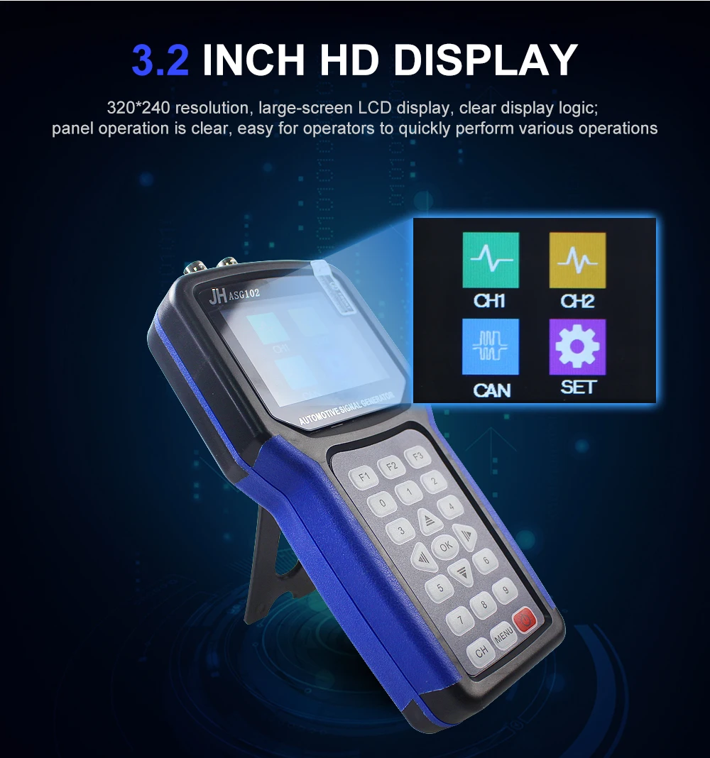
4. Friendly HMI: the instrument adopts the most simple design idea,
320*240 large-screen liquid crystal display, the display interface logic
is clear; the panel operation is clear, which is convenient for the
operator to quickly carry out various operations.
5. the appearance is small and convenient, using over injection molding,
good use of feel. The internal components are all imported, users can use
it with confidence!
(II) Main interface operation
1. After the instrument is turned on, enter the main operation interface
Press any button (except on/off key), the first item
(channel 1) will be selected by default.
Then use the “DIRECTION” button to switch the selected item.
3. After selecting the item, press the OK button to enter the corresponding
configuration interface.
(III) Signal generator operation
After booting into the main interface, press the button to select
“Channel 1” or “Channel 2”, then press “OK” to enter the signal
generator parameter setting interface.
Mainly configure output signal parameters such as frequency, amplitude,
duty cycle, waveform, X, Y.
CAN receiving operation
After booting into the main interface (or if you press the “MENU”
button directly on other interfaces, then will back to the main interface),
press “Can bus” and press “OK” to enter the CAN data receiving interface.
1. Data reception:
The data receiving area is for displaying each frame data received,
wherein the green marked frame data is the most recently received data.
The system can temporarily store 50 frames of data (loss of power loss).
To view the previous data of each frame, please stop data reception (press
“F3” to stop), and then use “ ” or “ ” key to view. The data
selected for each frame is marked in green.
2. Data analysis instructions:
StdId: Standard frame identifier.
ExtId: Extended frame identifier.
IDE: Identifies a standard frame or an extended frame. The main
difference is that the ID is different, the standard frame ID is
11-bit range(0-0x7ff); the extended frame ID is 29 (0-0x1fffffff).
RTR: The data frame is also a remote frame.
FMI: A 16-bit value indicating which filter the filter is filtered by.
data:data.
In the upper right corner of the data parsing area, “no data” will
always flash when no data is receiving. Once the data is received, green
“have data” will be displayed, as shown in Figure 1-10.
3. Receiving operation
(1)Connect Data line: First, insert the data receiving line into the
CAN receiver of the signal generator first, and put the “breaking
needle” on the other end. When measuring, connect the H and L lines of
the connector to H and L of the CAN communication interface of the car.
(2)Instrument operation: When preparing to receive data, firstly make
sure that the receiving status is “on”, if not press “F3” to turn it
on. Then select the communication baud rate, there are two ways: one is
manual adjustment, that is, manually press the “F1” key to select the
baud rate. When manually switching to a baud rate, if there is data coming,
the receiving area will immediately display the result. At this time stop
switching the baud rate, the baud rate will be the date what we want; the
other is automatic matching, that is, after pressing the "F2" button, the
system will automatically scans the baud rate, and simultaneously in the
data receiving area, the word "Scanning..." will be displayed to indicate
that it is being scanned. If data is received, the received data will be
displayed immediately on the screen and the baud rate will be set to the
value of current communication. If no baud rates have been received after
scanning, the screen will display: “Scan failed”, indicating that the
scan failed.
Note 1: The communication rate can be selected as 10K, 20K, 33.3K, 50K,
62.5K, 83.3K, 125K, 250K, 500K, 1M.
Note 2: If the baud rate is manually set and no data is received at each
baud rate, please check if the connection is loose or lost, if it matches
automatically .
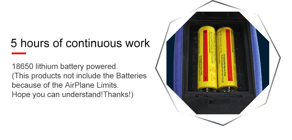
Due to air transportation restrictions, the product does not come with batteries


 배송기간
배송기간


