|
|
     aHR0cDovL2ZyZWVzaGlwLmNvLmty aHR0cDovL2ZyZWVzaGlwLmNvLmty
- 배터리 착탈식: 없음
- 최대 파형 캡처 속도: 30, 000wfm/s
- 기록 길이: 8M
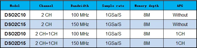
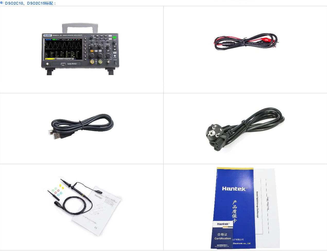
- 모델 번호: DSO2C10/2C15/2D10/2D15
- 실시간 샘플링 속도: 1GSa/S
- 디스플레이 해상도: 800*480픽셀
- 디스플레이 크기: 7 인치 및 위의
- 밴드 너비: 100-349mhz
- 디지털 채널: 2
- DIY 용품: 전기
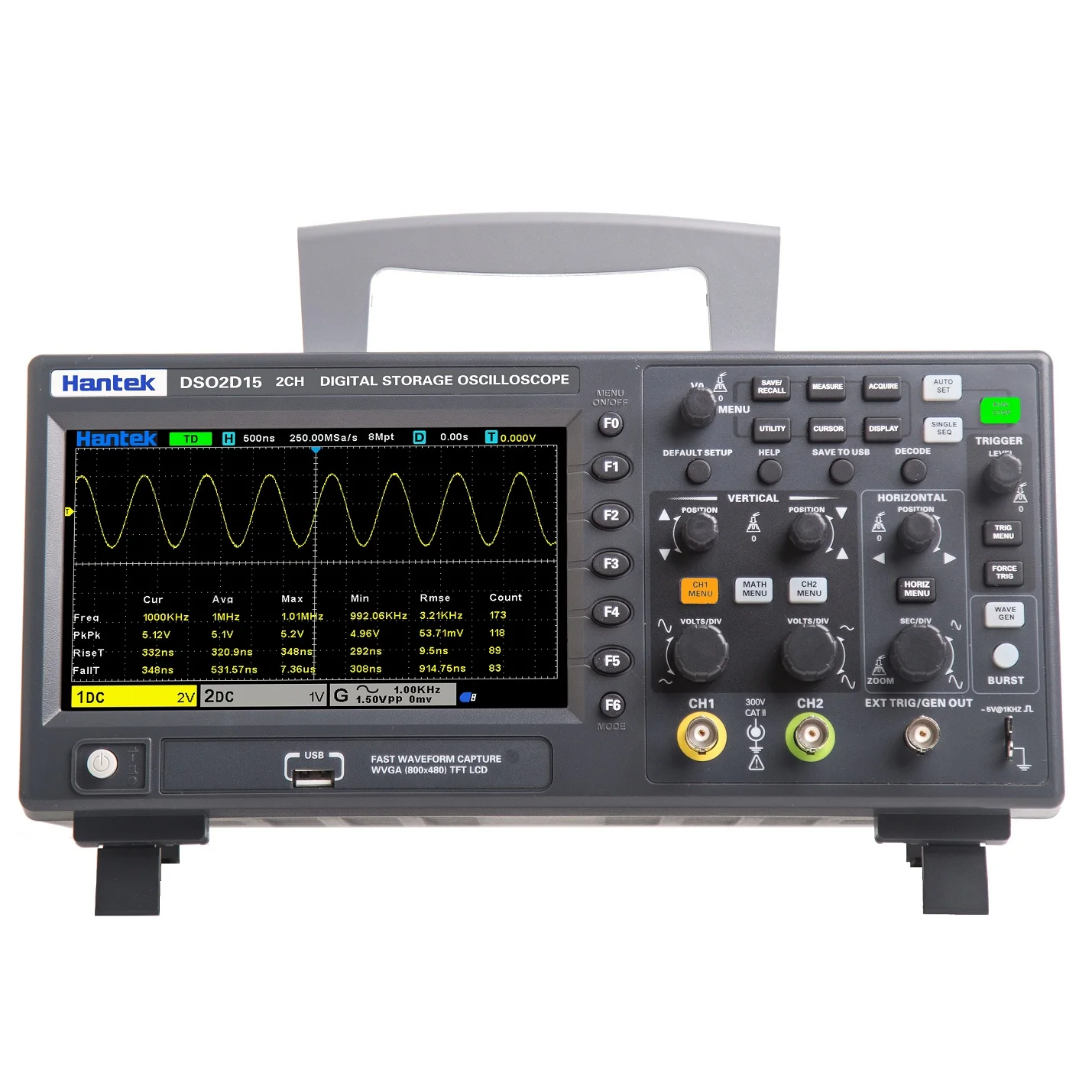
- 브랜드 이름: Hantek
- 근원: CN (정품)

한텍 신호 생성 디지털 오실로스코프 DSO2C10 2C15 2D10 2D15 듀얼 채널 오실로스코프 100M 150M 1GS/s
Features:
1) 2 channels, both are respectively controlled by independent knobes;
2)100 MHZ, 150MHZanalog channel bandwidth;
3)1 GSa/s real-time sample rate;
4) 8Mmemory depth;
5) Vertical range2mV/div ~ 10V/div;
6) Built-in 1 CH5MHz waveform generator;
7) Vertical resolution :8bit;
8) Trigger:Edge,Pulse width,Video,Slope,Overtime,Window,Pattern,Interval,Delay,UART,LIN,CAN,SPI,IIC;
9) CAN decode and protocol analysis:RS232/UART、I2C、SPI、CAN、LIN
10) Can save as multiple data formats, such as setting, waveform, referance waveform, CSV, picture;
11)5 bits digital voltage meter and 6 bits hardware frequency indicator function;
12) 32 kinds of auto measurements with statistics, real-time statistics of maxmum, minimum, standrad deviation and etc.;
13) 2 sets of digital voltmeter;
14) Support threshold testing, free measurements within the screen;
15) Abundant SCPIremote command control;
16) Many external interface:USB Host/Device.
NOTE:DSO2C10 and DSO2C15 have no waveform generator function!
Specifications:
Model |
DSO2D15 |
DSO2D10 |
DSO2C15 |
DSO2C10 |
Bandwidth |
150MHz |
100MHz |
150MHz |
100MHz |
Rising time in BNC position (typical) |
2.3ns |
3.5ns |
2.3ns |
3.5ns |
Vertical resolution |
8 bits resolution, each channel samples simultaneously |
Vertical sensitivity |
2mV/div to 10V/div |
Offset range |
2mV/div to 20mV/div, ±100mV; 50mV/div to 200mV/div, ±1V; |
500mV/div to 2V/div, ±10V; 5V/div to 10V/div, ±50V |
Mathematical operation |
+, -, ×, ÷, FFT |
FFT |
Window: Rectangle, Hanning, Hamming, Blackman, Bartlett, Flattop |
Bandwidth Limit |
20MHz |
Bass response(-3db) |
In BNC position ≤ 10Hz |
Vertical gain accuracy |
In ``normal`` or ``average`` acquisition mode, the accuracy of 10V/div to 10mV/div is ±3%; |
In ``normal`` or ``average`` acquisition mode, the accuracy of 5mV/div to 2mV/div is ±4% |
DC offset accuracy |
±0.1 div±2 mV±1% offset value |
Voltage measurement repeatability, average acquisition mode |
Under the same setting and environment, ≥16 waveforms are sampled, △V of any two averages: ±(3%×value+ 0.05 div) |
Note: Bandwidth reduced to 6MHz when using a 1X probe |
Trigger |
Trigger type |
Edge,Pulse width,Video,Slope,Overtime,Window,Pattern,Interval,Delay,UART,LIN,CAN,SPI,IIC |
Trigger level range |
±5 divisions from the center of the screen |
Trigger mode |
Auto,general,single |
Level |
CH1~CH2 |
±4 divisions from the center of the screen |
EXT |
0~3.3V |
Holdoff range |
8ns~10s |
Trigger level accuracy |
CH1~CH2 |
0.2 div×volts/div within ±4 divisions from the center of the screen |
EXT |
±(Set value× 6%+40mV) |
Edge trigger |
Slope |
Rising edge,falling edge,rising or falling edge |
Signal source |
CH1, CH2, EXT |
Pulse width trigger |
Polarity |
Positive polarity, negative polarity |
Condition(When) |
<, >, !=, = |
Signal source |
CH1~CH2, |
Pulse width range |
8ns ~ 10s |
Accuracy |
8ns |
Video trigger |
Signal standard |
NTSC, PAL |
Signal source |
CH1~CH2 |
Synchronization |
Scanning line, line number, odd field, even field, all field |
Slope trigger |
Slope |
rise, fall |
Condition(When) |
<, >, !=, = |
Signal source |
CH1 ~ CH2 |
Time range |
8ns ~ 10s |
Accuracy |
8ns |
Overtime trigger |
Signal source |
CH1~CH2, |
Polarity |
Positive polarity, negative polarity |
Time range |
8ns ~ 10s |
Accuracy |
8ns |
|
|
|
|
|


 배송기간
배송기간


