|
|
     aHR0cDovL2ZyZWVzaGlwLmNvLmty aHR0cDovL2ZyZWVzaGlwLmNvLmty
- 차원: -
- 작동 온도: -
- 출력 전압: DC 5V
- 정확도 등급: -
- 측정 에너지 범위: 0 - 2A
- 모델 번호: 4HH313882
- 최대 작동 전류: 19A & 밑에
- 전원 공급: DC
- 대형 활자: 디지털 전용
- DIY 용품: ELECTRICAL
- 브랜드 이름: OOTDTY
- 원산지: 중국
- Model: 9M52
- Working Current: 35 mA
Description:
brand new and high quality
Circuit Principle:
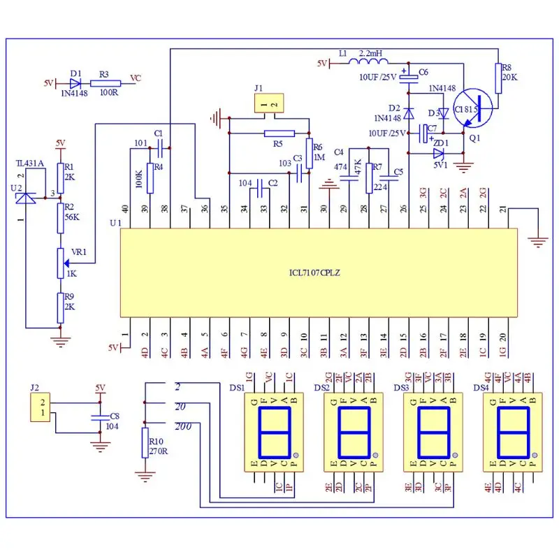
AMM-TE ammeter is mainly composed of ICL7107, power circuit, reference voltage source, input circuit and display circuit.
1.ICL7107 is a BCD output integral type A/D conversion chip, its internal includes ;linear amplification,analog switch, oscillation, display driving, etc,.
2.Power circuit is divided into positive power and negative power. Positive power is input by J2,C8 filtering. Negative is composed of R8, Q1, L1, C6, C7, D2, D3 and ZD1, which generate -5V voltage is input by chip 26th pin.
3.Reference voltage source is composed of R1, R2, VR1, R9, U2. 36-pin is reference voltage input pin. Adjust VR1 potentiometer to let 36-pin voltage be 100mV.
4.Input circuit is composed of J1, R5, R6 and C3. When the current of measured circuit passes through R5,it will generate a voltage on R5. This voltage will be input to chip 31-pin through R6 current limiting and be processed, C3 is input voltage filtering capacitor.
5.Display circuit is composed of DS1-DS4, D1, D4, 4 digital tubes can be drived directly by the chip. R10 is current limiting resistance of DS1-DS3 digital tubes decimal points.
Finished Product Debugging:
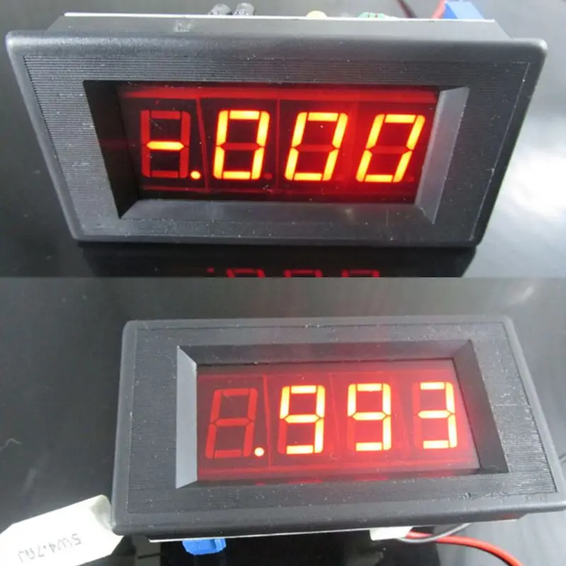
1.After connecting with DC 5V (please notice the polarity),the digital tube will display -.000 or .000,this is normal. cn1521689091ulta
2.Use multimeter to measure the voltage between chip 36-pin and 35-pin,and adjust VR1 potentiometer let it be 100mV.
Key Points Voltage Reference Value:
1.Chip 1-pin and 21-pin: 5V.
2.Chip 36-pin and 21-pin: 100mV,
3.Chip 26-pin and 21-pin: -5V.
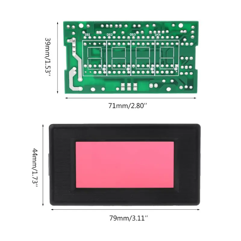
Specification:
Material: PCB + Metal + Plastic
Type: Digital Ammeter Kit
Panel Size:79 x 44mm / 3.11 x 1.73in
Mount Size:71 x 39mm / 2.8 x 1.53in
Quantity: 1 Pc
Electricity Parameters:
Working Voltage: DC 5V
Working Current: 35 mA
Accuracy: ±1mA
Measuring Range: 0 - 2A
Over Range Indication: Primacy Display 1/-1
Display Color: Red
Quantity: 1Set
Note:
Due to the difference between different monitors, the picture may not reflect the actual color of the item. Thank you!
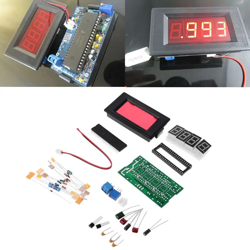
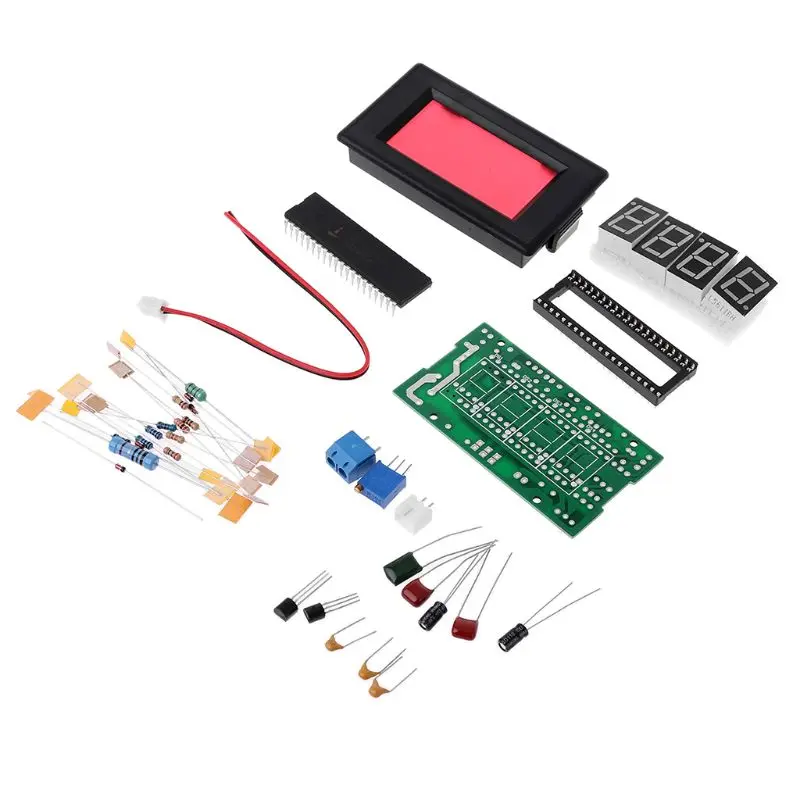
Package includes:
1Set x Digital Ammeter Kit
|
|
|
|
|


 배송기간
배송기간


