

LCR-TC2
1 Overview
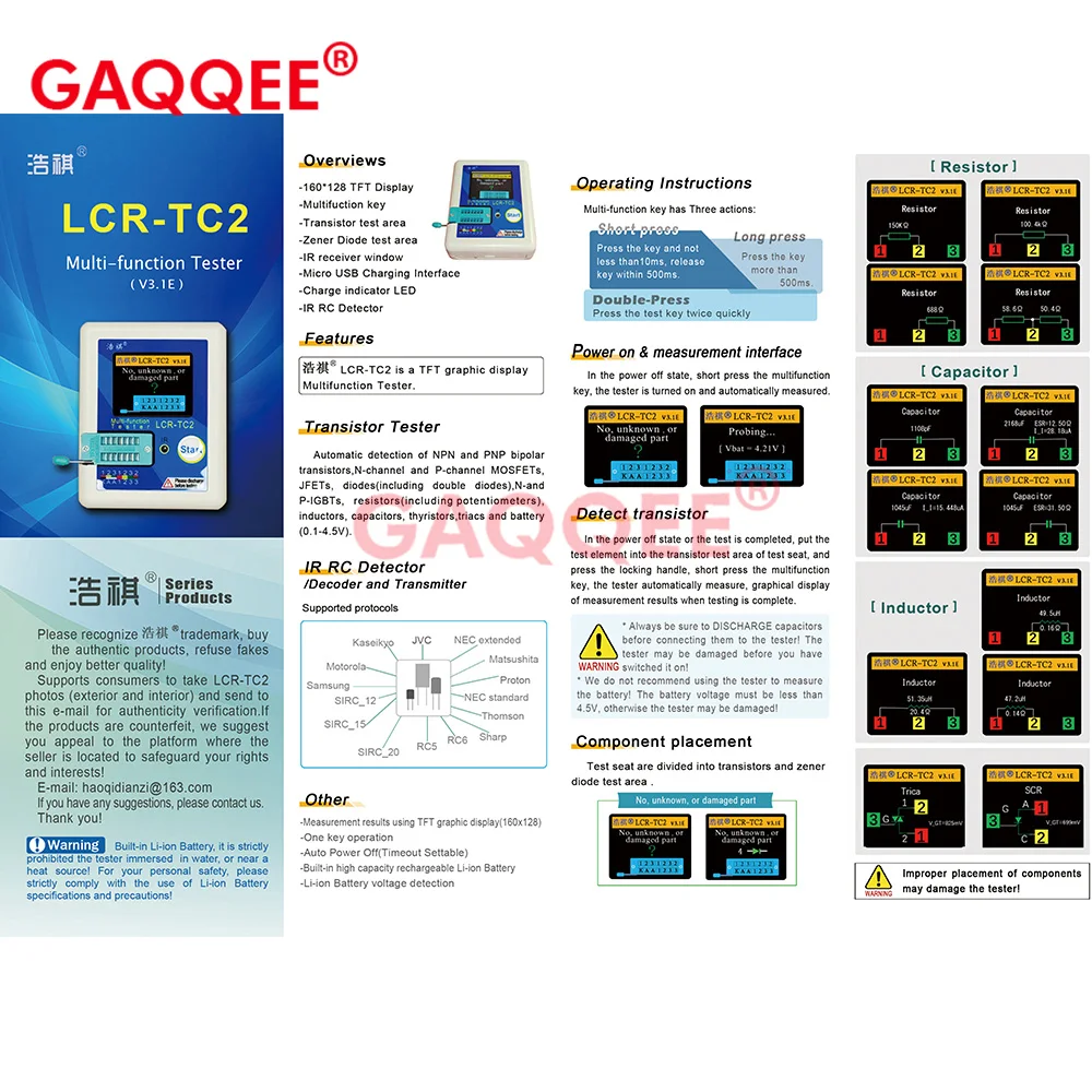
1.1 Introduction

1 - 128x128 TFT display
② - Multi function key
③ -Transistor test area
④ - Zener Diode test area
⑤ - IR receiver window
⑥ - Micro USB Charging Interface
⑦ - Charge indicator LED
1.2 Features
TC-T7-H is a TFT graphic display Multifunction Tester.
l Transistor Tester
Automatic detection of NPN and PNP bipolar transistors, N-channel and P-channel MOSFETs, JFETs, diodes (including double diodes), N- and P-IGBTs, resistors (including potentiometers), inductors, capacitors, thyristors, triacs and battery (0.1-4.5V)
- Automatic detection of zener diode(0.01-20V)
- Self test with automatic calibration
l IR decoder
- Support Hitachi IR coding
- IR waveform display
- Infrared receiving instruction
l Other
- Measurement results using TFT graphic display(160x128)
- One key operation
- Auto Power Off(Timeout Settable)
- Built-in high capacity rechargeable Li-ion Battery
- Li-ion Battery voltage detection
- Support Chinese and English
 Warning: Built-in Li-ion Battery, it is strictly prohibited the tester immersed in water, or near a heat source!
Warning: For your personal safety, please strictly comply with the use of Li-ion Battery specifications and precautions!
2 Operating Instructions
2.1 Key operational definitions
Multi-function key has two actions:
l Short press: Press the key and not less than 10 ms, release key within 1.5 seconds
l Long press: Press the key more than 1.5 seconds
2.2 Power on
In the power off state, short press the multifunction key, the tester is turned on and automatically measured.
l Power on & measurement interface

2.3 Detect transistor
In the power off state or the test is completed, put the test element into the transistor test area of test seat, and press the locking handle, short press the multifunction key, the tester automatically measure, graphical display of measurement results when testing is complete.
Warning: Always be sure to DISCHARGE capacitors before connecting them to the tester! The tester may be damaged before you have switched it on!
Warning: We do not recommend using the tester to measure the battery! The battery voltage must be less than 4.5V, otherwise the tester may be damaged!
l Component placement
Test seat are divided into transistors and zener diode test area, detailed in 1.1 Description.
l No, unknown, or damaged part


l Battery


l BJT(Bipolar Junction Transistor)


l Diode

l 2 Diodes


l MOSFET


l Thyristor

l Triac

l Capacitor

l Resistor


l Inductor

2.4 Selftest
Short all three Probes, short press the multifunction key, the tester will be automatically calibrates itself.
In addition to the calibration process when prompted disconnect external wiring short(Isolate the probes), without the need for other operations.
l Calibrating

l Isolate the probes

l Selftest End

Warning: Do not carry out other operations in the calibration process, so as not to affect the calibration accuracy!
2.5 Detect Zener diode
In the power off state or the detection is completed, put the Zener diode into the Zener diode test area of test seat, and press the locking handle, short press the multifunction key, the tester automatically measure, graphical display of measurement results when testing is complete.

Warning: Do not put the component into transistor test area, otherwise it is impossible to test zener diode!
2.6 IR decoder
After the component detection is completed, the infrared remote control at the tester "IR" test hole, press the remote control key, the tester will be display the user code & data code and the corresponding infrared waveform after the successful decoding.
If decoding failure, the tester cannot display the user code and data code.
The dot at the top right corner to indicate whether it has received the remote control infrared data, red represents infrared data is being received, blue represents decoding success.

 Information:The IR decoder only support Hitachi IR format.
2.7 Power off
The Multifunction Tester with automatic shutdown and manual shutdown.
l Automatic shutdown
When the component detection completed or IR decoding completed and after reaching the automatically shut down time, the tester automatically shut down.
Automatic shutdown time can be set by the hardware jumpers, timeout support for 10s, 15s, 20s and 25s. Factory set to 20s.

Warning: Adjust the automatic shutdown time required to open the housing, and use an electric soldering iron solder the jumpers.
 Attention:Please do ESD protection!
l Manual shutdown
Long press the multifunction key to force a shutdown in any state, while the measuring element is included.
2.8 Built-in Li-ion Battery voltage measurement
The built-in Li-ion Battery voltage is measured before detection, when the battery voltage is less than 3.0V will force shutdown, then please charging.

2.9 Charging the Battery
The tester has a standard Micro USB interface, please use an external 5V power supply or USB power charging.
Information:Red LED indicates is charging, green LED indicates charging is complete.
Warning: Charging input voltage up to 6V, do not exceed the top voltage, or it will damage the tester, and could cause the battery to explode!

3 Performance Parameters
Multifunction Tester can automatically identify elements and automatic detection of pin layout, and automatic switching range.
The main performance parameters are as follows:

Note①: Iceo, Ices, Uf displayed only when effective
Note②: Diode Capacitance, Ir(Reverse Current) displayed only when effective
Note③: Displayed only when has protecting diode
Note④: ESR, Vloss displayed only when effective
Note⑤: Measurement of inductors with resistance below 2100Ω


 배송기간
배송기간


