|
|
     aHR0cDovL2ZyZWVzaGlwLmNvLmty aHR0cDovL2ZyZWVzaGlwLmNvLmty
- 스마트 기기: no
- DC 전류: 1A
- AC 전류: no
- DC 전압: 9V
- AC 전압: no
- 작동 모드: Digital
- 측정 용량 범위: as the description
- 측정 저항 범위: as the description
- 모델 번호: LCR-T4 GM328A GM328B M328TC-T7-H LCR-T7 LCR-TC1 LCR-TC2
- 차원: as the description
- 작동 온도: 0 - 40℃
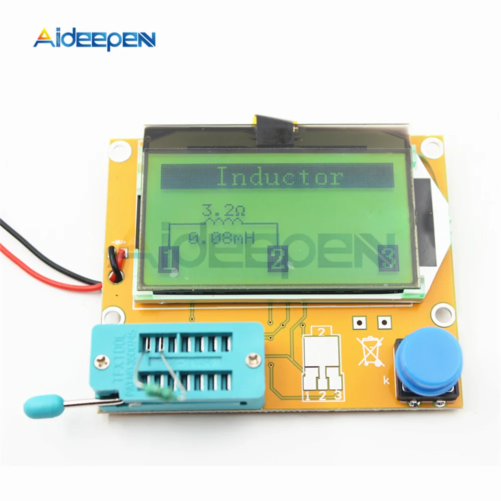
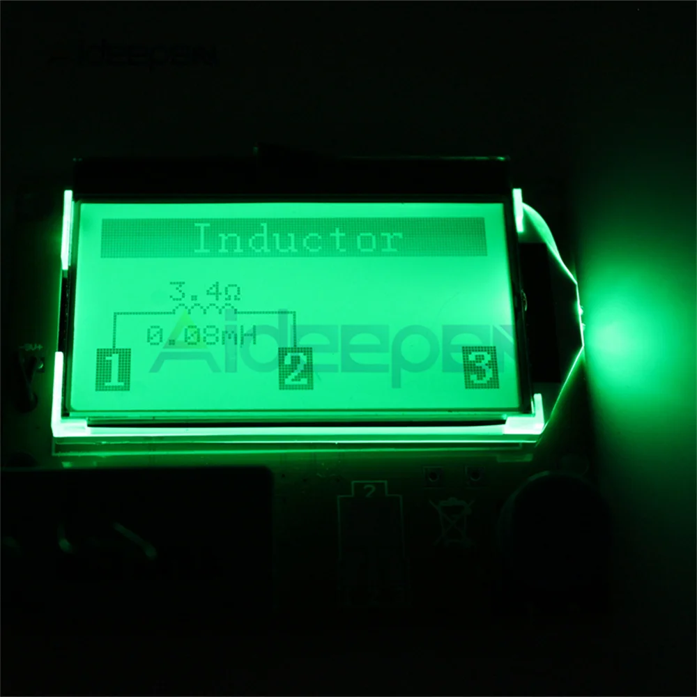
- 측정 인덕턴스 범위: as the description
- 대형 활자: 디지털 디스플레이
- DIY 용품: 전기
- 브랜드 이름: Aideepen
- 근원: CN (정품)
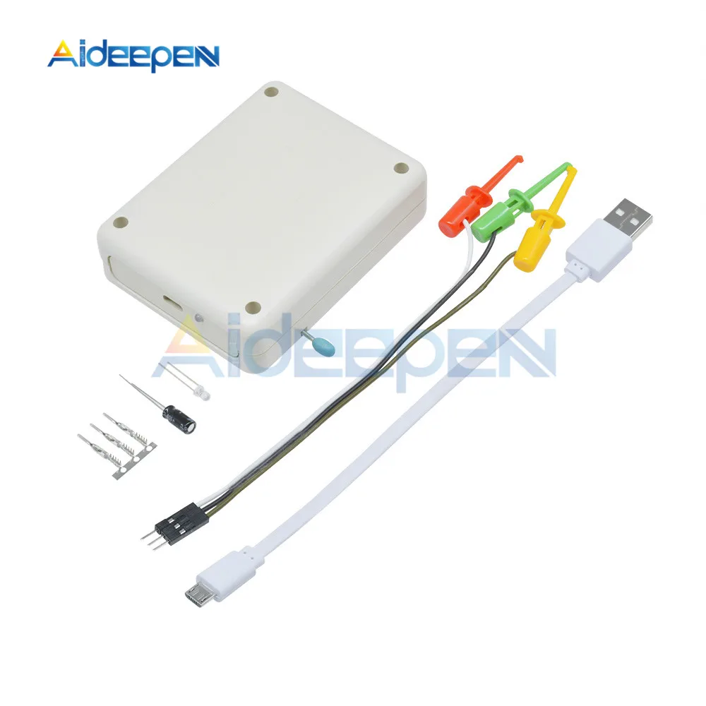
옵션정보[(202074810)LCR-T4 Button] [(350686)LCR-T4 Battery Case] [(350686)LCR-T4 Battery Case] [(350852)LCR-T4 Test Hook] [(350852)LCR-T4 Test Hook] [(10)LCR-T4 Test Hook] [(10)LCR-T4 Test Hook] [(29)TC-T7-H] [(29)TC-T7-H] [(94)LCR-T7] [(94)LCR-T7] [(173)LCR-TC1] [(173)LCR-TC1] [(175)LCR-TC2] [(175)LCR-TC2] [(193)LCR GM328 EN Ver] [(193)LCR GM328 EN Ver] [(366)LCR GM328 RU Ver] [(366)LCR GM328 RU Ver] ? ? High Quality LCR-T4 ESR Meter Transistor Tester Diode Triode Capacitance SCR Inductance GM328 TC-T7-H LCR-T7 LCR-TC1 LCR-TC2 ? ? Description: ? LCR-T4 Detailed Introduction: Features : ? 2021 latest M328 version of the software ,more functions.Chip: Atmega328
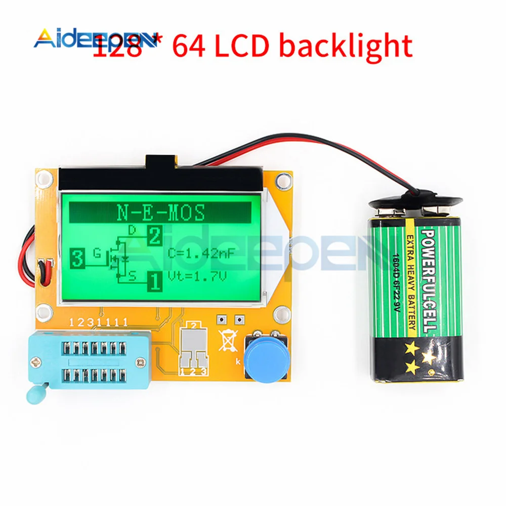
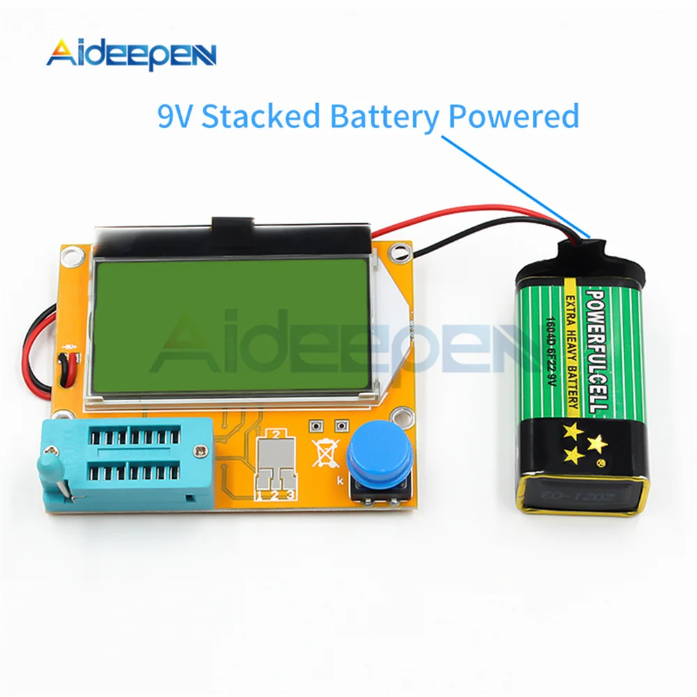
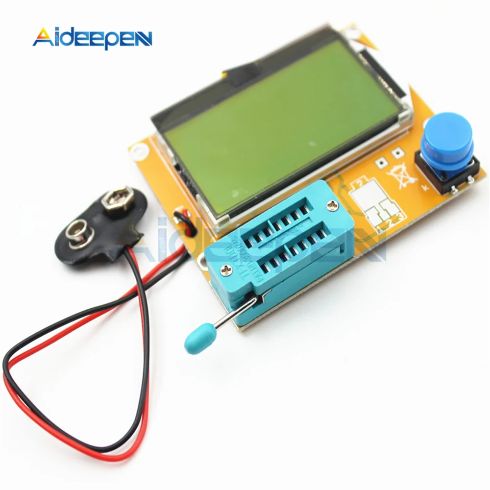
? 128*64 big Backlight LCD display,only 2mA when stand by. ? Using 9V battery?(Not included)
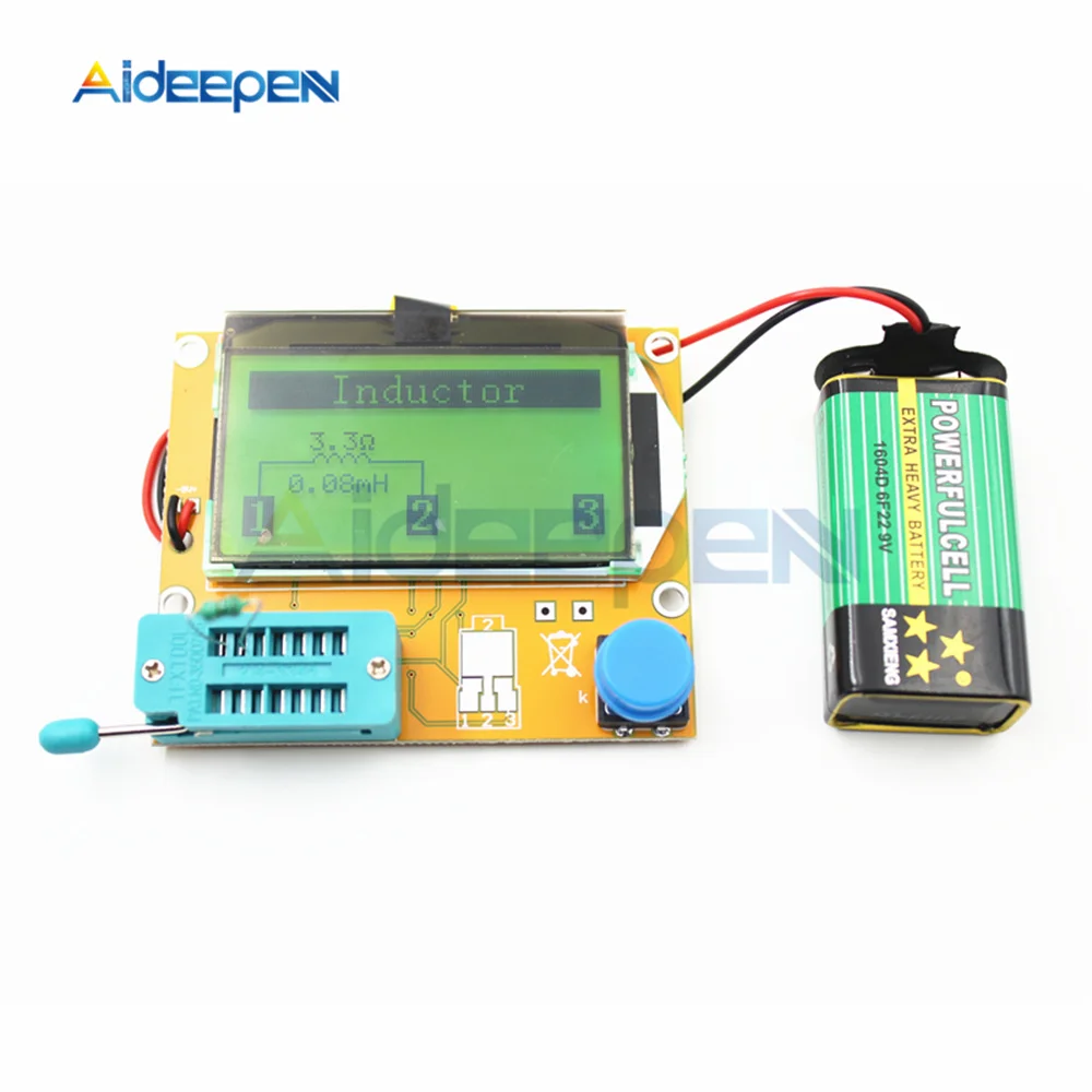
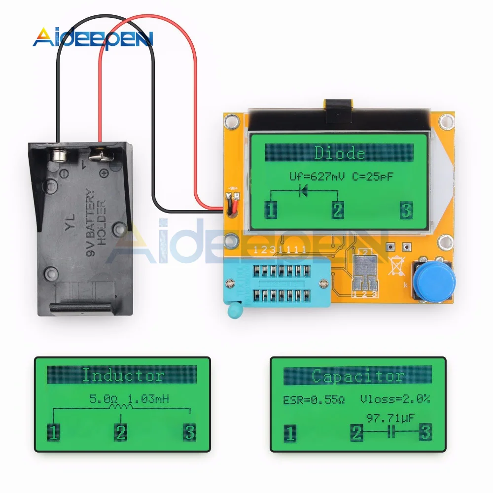
? Inductors, capacitors , diodes, dual diode , mos, transistor, SCR , the regulator, LED tube , ESR,
? Resistance,Adjustable potentiometer
? Resistance : ?0.1 ohm resolution, maximum 50M ohm
? Capacitor : ?25pf -100,000 uf ? Inductors : ? 0.01mh-20H ? Automatic detection of NPN and PNP transistors, n-channel and p-channel MOSFET, diode (including double diode), thyristor, transistor, resistor and capacitor and other components ? Automatic test the pin of a component, and display on the LCD ? Can detect the transistor, MOSFET protection diode amplification coefficient and the base to determine the emitter transistor forward biased voltage ? Measure the gate and gate capacitance of the MOSFET threshold voltage
? Use 12864 liquid crystal display with green backlight
Specifications:?For you reference
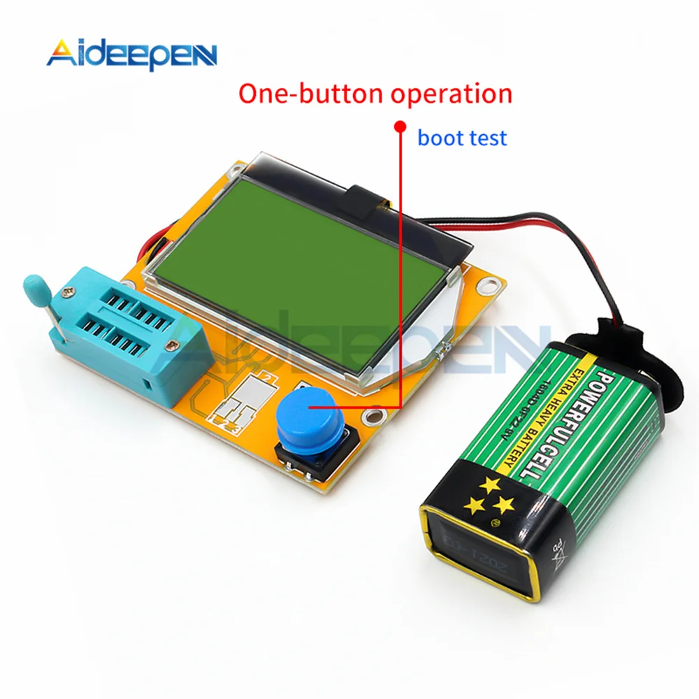
1: ?One -button operation, automatic shutdown .
2: ?Only 20nA shutdown current.
3: ?Automatically detect NPN, PNP bipolar transistors , N -channel and P -channel MOS FET, JFET , diodes , two diodes, thyristors small power unidirectional and bidirectional thyristor. 4: ?Automatic identification components pin arrangement .
5: ?Measuring bipolar transistor current amplification factor and base - emitter threshold voltage.
6: ?Via the base - emitter threshold voltage and high current amplification factor to identify Darlington transistors.
7: ?Can detect bipolar transistors and MOS transistors protection diodes.
8: ?Measuring the gate MOS FET threshold voltage and the gate capacitance. 9: ?Can simultaneously measure two resistors and resistor symbol is displayed. ? ? ?Displayed on the right with a decimal value of 4 . ? ? ?Resistance symbol on both sides shows the pin number. ? ? ?So you can measure the potentiometer. ? ? ?If the potentiometer wiper is not transferred to an extreme position , ? ? ?we can distinguish the middle and both ends of the pin. 10: ?Resistance measurement resolution is 0.1 ohms , 50M ohms can be measured .
11: ?Can measure capacitanceCan measure capacitance of 30pF-100mF , resolution 1pF. 12: ?2uF more capacitors can simultaneously measure the equivalent series resistance ESR values. ? ? ? ?The two can be displayed with a decimal value , resolution 0.01 ohms. 13: ?Can be in the correct order and the diode symbol display two diodes , and gives the diode forward voltage.
14: ?LED is detected as a diode forward voltage higher . Combo of the LED is identified as two diodes.
15: ?Eeverse breakdown voltage is less than 4.5V Zener diode can be identified. 16: ?Can measure a single diode reverse capacitance. ? ? ? ?If the bipolar transistor connected to the base and collector or emitter of a pin , ? ? ? ?it can measure the collector or emitter junction reverse capacitance . 18: ?can be obtained with a single measurement rectifier bridge connection.
TC-T7-H LCR-T7 LCR-TC1 LCR-TC2 Detailed Introduction:
What's the difference between 3 versions?
T7 / TC1:color screen, two functions are the same! T7 is slightly faster! The TC1 screen is slightly larger and they are all powered by lithium batteries. In addition to measuring resistance, capacitance, inductance, diodes, MOS transistors, thyristors, it can also measure additional voltage regulators, infrared decoding (limited to for Hitachi format) T7H:is an upgraded version of T7, Up-to-date / fastest version
TC-T7-H
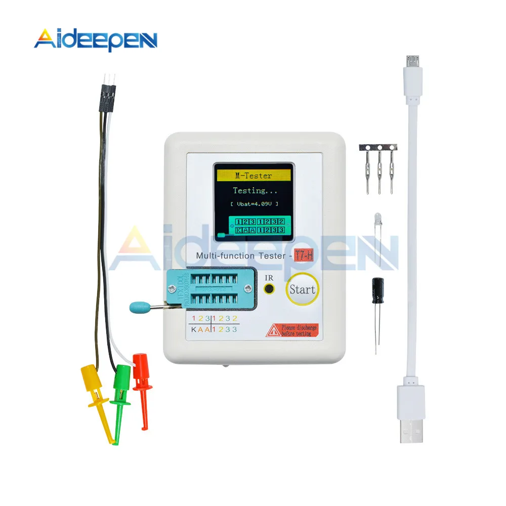
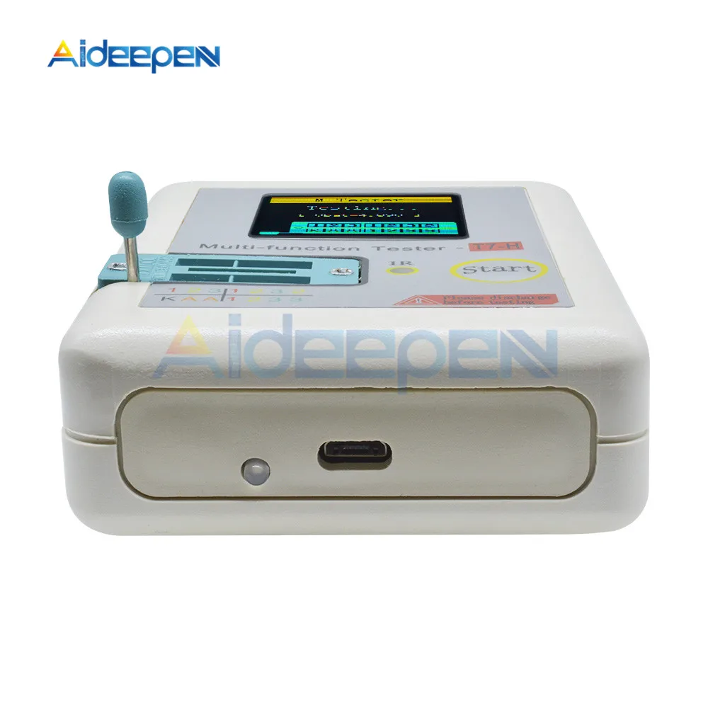
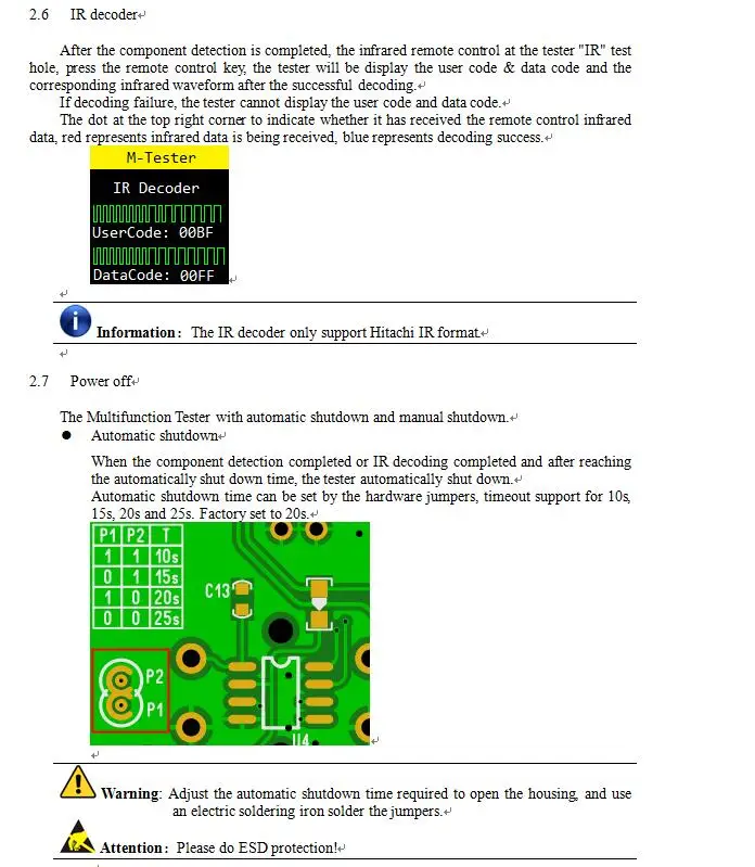
128x128 TFT display Multi function key Transistor test area Zener Diode test area IR receiver window Micro USB Charging Interface Charge indicator LED
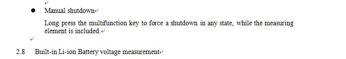
Features: TC-T7-H? is a TFT graphic display Multifunction Tester. Transistor Tester: Automatic detection of NPN and PNP bipolar transistors, N-channel and P-channel MOSFETs, JFETs, diodes (including double diodes), N- and P-IGBTs, resistors (including potentiometers), inductors, capacitors, thyristors, triacs and battery (0.1-4.5V) Automatic detection of zener diode(0.01-20V) Self test with automatic calibration IR decoder: Support Hitachi IR coding IR waveform display Infrared receiving instruction Other: Measurement results using TFT graphic display(160x128) One key operation Auto Power Off(Timeout Settable) Built-in high capacity rechargeable Li-ion Battery Li-ion Battery voltage detection Support Chinese and English Performance Parameters: Multifunction Tester can automatically identify elements and automatic detection of pin layout, and automatic switching range. The main performance parameters are as follows:
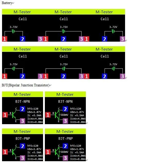
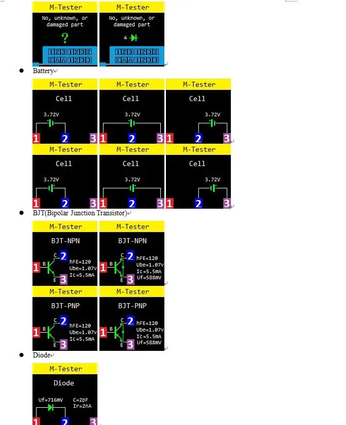
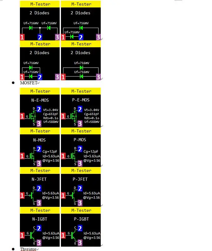
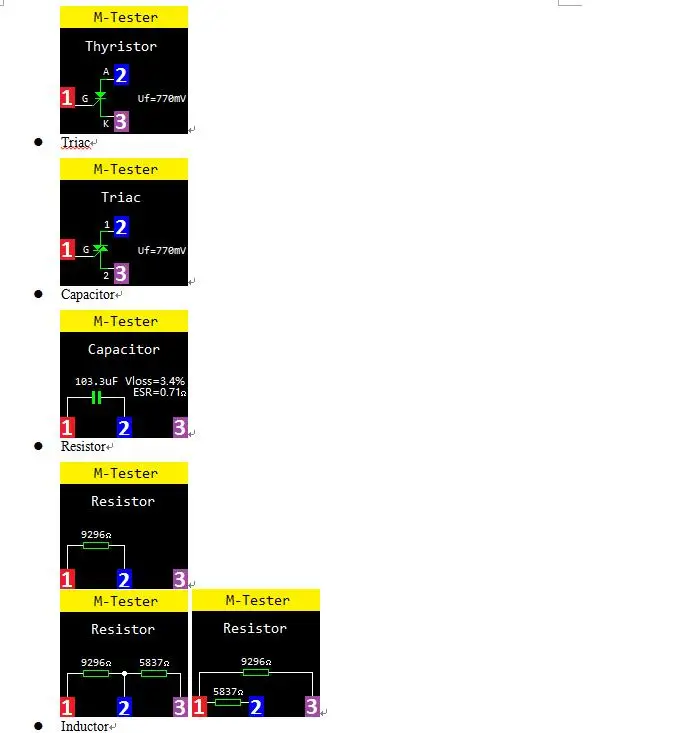
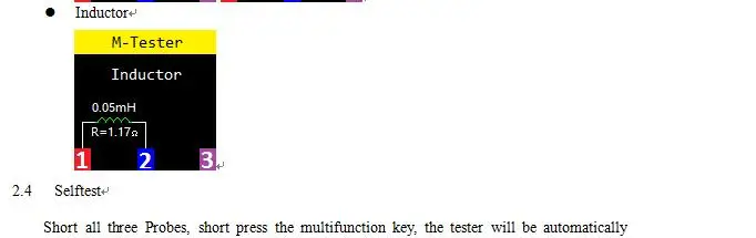
Component | Range | Parameter Description | BJT | - | hFE(DC Current Gain), Ube(Base-Emitter Voltage), Ic(Collector Current), Iceo(Collector Cut-off Current (IB=0)), Ices(Collector short Current), Uf(Forward Voltage of protecting diode) ③ | Diode | Forward Voltage <4.50V | Forward Voltage, Diode Capacitance, Ir(Reverse Current) ② | Double Diodes | Forward Voltage | Zener Diode | 0.01-4.50V (Transistor test area) | Forward Voltage, Reverse Voltage | 0.01-20V (Zener Diode test area) | Reverse Voltage | MOSFET | JFET | Cg(Gate Capacitance), Id(Drain Current) at Vgs(Gate to Source Threshold Voltag), Uf(Forward Voltage of protecting diode) ④ | IGBT | Id(Drain Current) at Vgs(Gate to Source Threshold Voltag), Uf(Forward Voltage of protecting diode) ④ | MOSFET | Vt(Gate to Source Threshold Voltag), Cg(Gate Capacitance), Rds(Drain to Source On Resistance), Uf(Forward Voltage of protecting diode) ④ | Thyristor | Igt(Gate trigger current )<6mA | Gate trigger voltage | Triac | Capacitor | 25pF-100mF | Capacitance, ESR(Equivalent Series Resistance),? Vloss ① | Resistor | 0.01-50MΩ | Resistance | Inductor | 0.01mH-20H | Inductance, DC Resistance ⑤ | Battery | 0.1-4.5V | Voltage, Battery Polarity |
Note①: Iceo, Ices, Uf displayed only when effective Note②: Diode Capacitance, Ir(Reverse Current) displayed only when effective Note③: Displayed only when has protecting diode Note④: ESR, Vloss displayed only when effective Note⑤: Measurement of inductors with resistance below 2100Ω FAQ
Question | Cause | Solution | Cannot power on | Built-in Li-ion Battery is dead | Charging the Li-ion Battery, charging methods see section 2.9 | Inaccurate measurements | Inaccurate calibration parameters | Please re-calibration, see section 2.4 |
|
|
|
NOTE: 1.Built-in Li-ion Battery, it is strictly prohibited the tester immersed in water, or near a heat source! 2.For your personal safety, please strictly comply with the use of Li-ion Battery specifications and precautions! TCR-T7
160x128 TFT display Multi function key Transistor test area Zener Diode test area IR receiver window Micro USB Charging Interface Charge indicator LED
Features:
TC-V2.12k is a TFT graphic display Multifunction Tester. Transistor Tester Automatic detection of zener diode0.01-30V Self test with automatic calibration
IR decoder Support Hitachi IR coding IR waveform display Infrared receiving instruction
Other Measurement results using TFT graphic display(160x128) One key operation Auto Power Off(Timeout Settable) Built-in high capacity rechargeable Li-ion Battery Li-ion Battery voltage detection Support Chinese and English
Warning: Built-in Li-ion Battery, it is strictly prohibited the tester immersed in water, or near a heat source! Warning: For your personal safety, please strictly comply with the use of Li-ion Battery specifications and precautions!
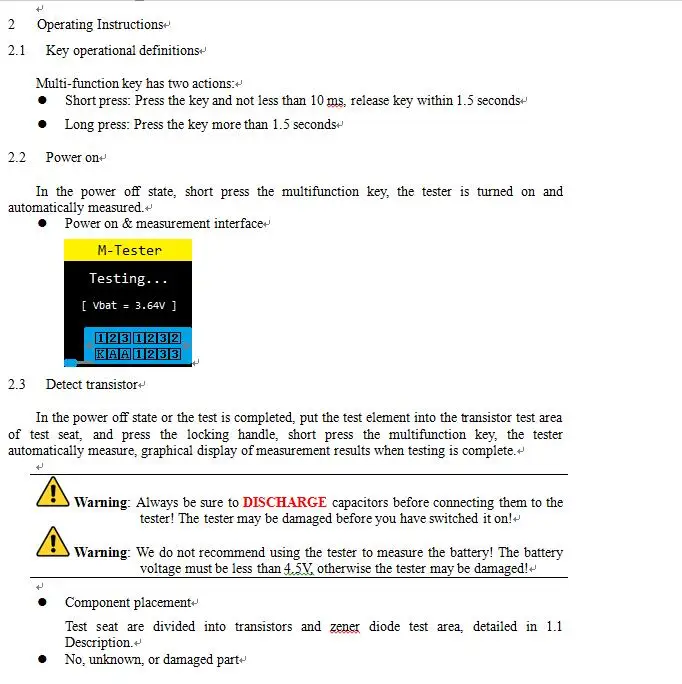
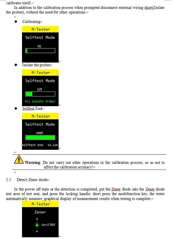
Operating Instructions:1.Key operational definitionsMulti-function key has two actions: -Short press: Press the key and not less than 10 ms, release key within 1.5 seconds -Long press: Press the key more than 1.5 seconds
2.Power onIn the power off state, short press the multifunction key, the tester is turned on and automatically measured. -Power on & measurement interface
3.Detect Transistor
In the power off state or the test is completed, put the test element into the transistor test area of test seat, and press the locking handle, short press the multifunction key, the tester automatically measure, graphical display of measurement results when testing is complete.
Warning: Always be sure toDISCHARGEcapacitors before connecting them to the tester! The tester may be damaged before you have switched it on! Warning: We do not recommend using the tester to measure the battery! The battery voltage must be less than 4.5V, otherwise the tester may be damaged!
LCR-TC1
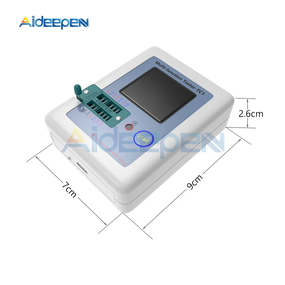
Self test with automatic calibration Size: 70*90*26m/ 2.71x3.58x1.10 inch Display:TFT Screen, Color Screen Diode Range: less than 4.5V Zener Diode:Transistor Detect Area: 0.01-4.5V Zener Diode Detect Area: 0.01-30V Triac Range: IGT less than 6mA Capacitance: 25pF-100mF Resistor: 0.01-50MΩ Inductance: 0.01mH-20H Power Voltage: 3.7V Power: Built-in Rechargeable Lithium Battery Measurement results using TFT graphic display (160x128) One-button operation Auto power off (timeout setting) Built-in high-capacity rechargeable lithium-ion battery Lithium-ion battery voltage detection Support Chinese and English Warning: Built-in lithium-ion battery, it is strictly forbidden to immerse the tester in water or near heat source! Warning: For your personal safety, please strictly observe the specifications and precautions for using lithium-ion batteries! Transistor Detection: After the power-off state or test is completed, put the test component into the transistor test area of the test socket, press the lock handle, press the multi-function key, the tester automatically measures, and the measurement result is displayed at the end of the test. Warning: Always discharge the capacitor before connecting them to the tester! The tester may be damaged before you turn it on! Warning: We do not recommend using a tester to measure the battery! The battery voltage must be less than 4.5V, otherwise the tester may be damaged! Component placement: The test socket is divided into transistor and Zener diode test areas, as described in 1.1.
LCR GM328 Detailed Introduction
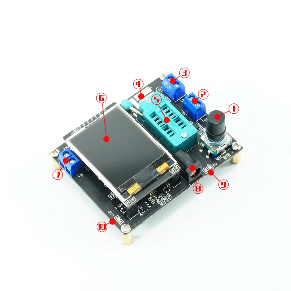
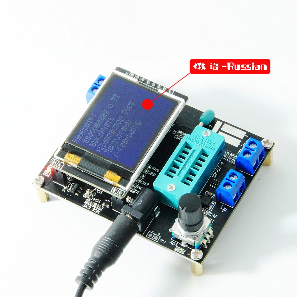
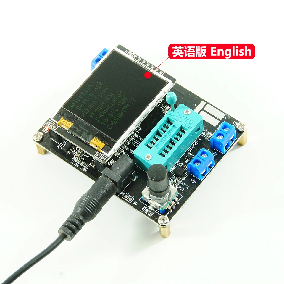
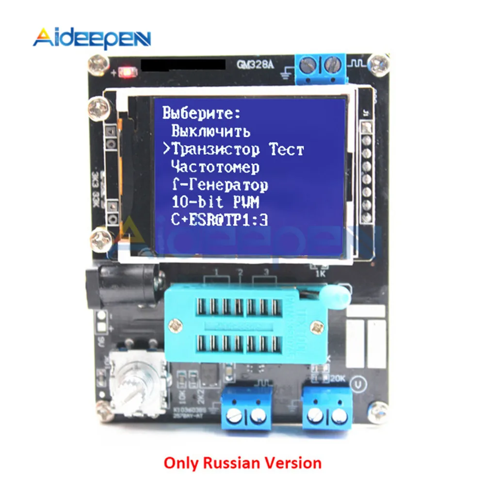
Note:The following functions are all available in English version, some functions are not updated in Russian version Description: Input voltage: DC 6.8V-12V Working voltage: about 30mA, measured when inputting 7.5V DC voltage Transistor tester control The tester is controlled by a rotary encoder switch, The rotary encoder switch can have a total of 6 operations, short press, long press, left rotation, right rotation, hold left rotation, hold right rotation. In the shutdown state, short press once to turn on the power and start the test. After a test is completed, if the device is not detected. Long press the switch or the left and right rotary switch to enter the function menu. After entering the function menu, the left or right rotary switch can be selected up and down in the menu item. To enter a function item, short press the switch once. When you need to exit from a function, press and hold the switch. ①Control button ②Square wave and PWM outputinterface ③voltage measurement interface ④Original test bit ⑤In the original test base ⑥160×128 full color display ⑦Frequency messurement interface ⑧Power adapter socket ⑨9V battery contact 9V ⑩Work indicator Version function comparison Features | English | Russian | Switch off | Yes | Transistor | Yes | f-Generator | Yes | 10-bit PWM | Yes |  :3 :3
| Yes | C+ESR@TP1:3 | Yes | 1-||-3 | Yes | DS18B20 | Yes | No | C(uF)-correction | Yes | IR_Decoder | Yes | No | IR_Encoder | Yes | No | DHT11 | Yes | No | SelfTest | Yes | Voltage | Yes | FrontColor | Yes | No | BackColor | Yes | No | Show?data | Yes |
Test device The tester has 3 test points, TP1, TP2, TP3. The distribution of these three test points in the test block is as follows: 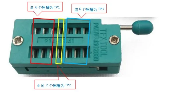
On the right side of the test seat is the test position of the patch component, there are numbers 1, 2, and 3 respectively, each representing TP1, TP2, and TP3 When testing a component with only 2 pins, the pins are not divided into the test order, 2 pins are arbitrarily selected for 2 test points, and the device pins with 3 pins are placed in three test points respectively, regardless of the order. After the test, the tester automatically recognizes the pin name and test point of the component, and displays it on the screen. When testing a component with only 2 pins, if two test points TP1 and TP3 are used, it will automatically enter the continuous test mode after the test is completed, so that the components on TP1 and TP3 can be continuously and synchronously measured without pressing the switch. If you are using the "TP1 and TP2" or "TP2 and TP3" test, only test once. To test again, press the switch once. Before testing the capacitor, discharge the capacitor first, and then insert the test socket for measurement, otherwise the single-chip microcomputer of the tester may be damaged. 1. Calibration The tester calibration is used to eliminate the errors of its own components and make the final test results more accurate. Calibration is divided into quick calibration and full-function calibration. The operation method of quick calibration: short-circuit the three test points TP1, TP2, and TP3 with wires, then press the test button while observing the screen. The color of the screen will change to black and white. After the prompt message "Selftest mode..?" appears, press the test button to enter the quick calibration process; if the prompt message "Selftest mode..?" appears, 2 seconds If there is no button in the clock, a normal test process is performed, and finally the resistance value of the three test points of TP1, TP2 and TP3 is displayed. After entering the quick calibration process, some data will appear on the screen, just ignore it. Wait until a flashing string appears on the screen After "isolate Probes!", remove the wires that short-circuit TP1, TP2, and TP3. After the character string "Test End" appears on the screen, the quick calibration is completed. When calibrating for the first time, use the full-function calibration method. Full function calibration needs to be entered from the function menu, and a 220nf capacitor is also required. The full-function calibration performs a more comprehensive calibration process and will take longer. After entering the function menu, rotate the test button to the menu item "Selftest", and then press the test button to enter the full-function calibration process. The flashing string "short Probes!" appears on the screen, which is the same as the quick calibration. Use wires to short-circuit the three test points and wait for the calibration process to proceed. When the flashing string "isolate Probes!" appears on the screen, remove the wires that short-circuit the three test points and continue to wait for the calibration process to proceed. When the character string "1-||-3> 100nf" is output, install the prepared 220nf capacitors on the test points TP1 and TP3. Wait until the screen prompts "Test End", the full-function calibration process is complete. 2. Function menu 2.1 Switch off 2.2 Transistor 2.3 Frequency Measuring frequency. Long press the test button to exit the frequency measurement function. The frequency measurement range is from 1Hz to above 1MHz. When the measured frequency is lower than 25KHz, the period is displayed 2.4 f-Generator Square wave generator, there are multiple square wave frequencies to choose from, left or right rotation test button to switch different square wave frequencies, long press the test button to exit the square wave generator. 2.5 10-bit PWM Pulse signal generator, rotate the test button left or right to adjust the duty cycle of the pulse, from 1%-99%. Long press the test button to exit the pulse signal generator. 2.6 C+ESR@TP1:3 Capacitance online measurement function, two wires can be drawn from TP1 and TP3, and the capacitance value and ESR of 2uF-50mF capacitors can be measured online. Note that the measured capacitance must be completely discharged before the test. If it is online measurement, the circuit where the capacitance is located must be completely disconnected It can only be carried out after electricity. 2.7 The continuous resistance measurement method continuously tests the resistance and inductance values installed on TP1 and TP3. The inductance of the measured resistance is less than 2100 ohms, and the inductance measurement range is 0.01mH-20H. Long press the test button to exit. 2.8 1-||-3 Capacitance continuous measurement method continuously tests the capacitance value installed on TP1 and TP3. For small-capacity capacitors, only this method can be used to measure the capacitance value. Measure the equivalent series resistance (ESR) of capacitors larger than 90nF, and the resolution of ESR is 0.01Ω. Capacitors above 5000pF show the rate of voltage drop after charging. 2.9 DS18B20Russian version does not have this function DS18B20 is a temperature sensor that uses single-bus communication to transmit data. It has the same package (TO-92) as a triode. The figure below shows the pin distribution of DS18B20. 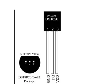 After entering the DS18B20 test function, the second line of the display shows the connection relationship between the test socket and DS18B20, "1=GND 2=DQ 3=VDD", which means TP1 is connected to DS18B20 GND, TP2 is connected to DS18B20 DQ, and TP3 is connected to DS18B20 VDD . The tester cannot automatically recognize DS18B20, so you must follow the instructions on the second line to install Install DS18B20. The tester can read the 12-digit temperature results measured by DS18B20, and display the corresponding temperature in Celsius on the third line with a resolution of 0.0625°C. Scratchpad: The contents of the 8 storage units inside the DS18B20 read by the tester plus the CRC check value of the last byte. A total of 9 bytes. Scratchpad? ? ? ? ? ? ? ? ? BYTE TEMPERATURE LSB | 0 | TEMPERATURE MSB | 1 | TH/USER BYTE 1 | 2 | TL/USER BYTE 2 | 3 | CONFIG | 4 | RESERVED | 5 | RESERVED | 6 | RESERVED | 7 |
For example, the value read once is Scratchpad: EC014B467FFF0C102A has the following relationship:
Scratchpad? ? ? ? ? ? ? ? ?Value ? ? ? BYTE TEMPERATURE LSB | EC | 0 | TEMPERATURE MSB | 01 | 1 | TH/USER BYTE 1 | 4B | 2 | TL/USER BYTE 2 | 46 | 3 | CONFIG | 7F | 4 | RESERVED | FF | 5 | RESERVED | 0C | 6 | RESERVED | 10 | 7 |
64-bit ROM: The globally unique device ID of each DS18B20 read by the tester. The ID has a length of 64 bits. Divided into 3 parts.
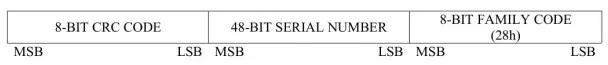
For example, the 64-bit ROM read by a DS18B20 is 64-bit ROM: 28FF4D58361604A1 Then there is 8-BIT FAMILY CODE | 28 | 48-BIT SERIAL NUMBER | 041636584DFF | 8-BIT CRC CODE | A1 |
Note: Except that the temperature value (TEMP) is in decimal, the rest are in hexadecimal. The temperature measurement range of DS18B20 is -55℃-125℃. Long press the test button to exit this function. 2.10 C(uF)-correction This function is used to correct the measured value of large-capacity capacitors. The default value is 0%. That is, there is no correction, the setting range is -0.2%-8%, when it is a positive value, it will reduce the measured value of the capacitance, and when it is a negative value, it will increase the measured value of the capacitance. After setting, long press the test button to exit. 2.11 IR_DecoderRussian version does not have this function Infrared remote control decoding function. This function requires a 1838 integrated infrared receiver (pulse type). After entering this function, observe the prompt on the display screen. The second line will display the character string ""1=DOUT 2=GND 3= VCC", the character string means the connection relationship between the 3 test points on the tester and the infrared receiver, and the connection must be strictly in accordance with the instructions. Only one infrared receiver can be installed on the test seat empty or correctly. For other components, it is not allowed to short-circuit the test points with wires to avoid unpredictable failures. The following figure shows the installation direction of an example infrared receiver. 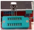 TP1 is connected to the DOUT pin of the infrared receiver, TP2 is connected to GND, and TP3 is connected to VCC. The infrared remote control decoding function supports two infrared remote control encoding formats. Format one 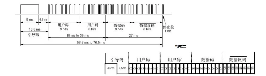 The above two formats are roughly the same, the difference lies in the length of the pilot code. Format one is 9MS and format two is 4.5MS. Infrared remote control decoding function uses uPD6121 to indicate format one, and TC9012 to indicate format two. Instructions : The infrared remote control decoding function can only be accessed from the function menu. Before entering the infrared remote control decoding function, there must be no components on the test base and the square wave output terminal. Enter the infrared remote control decoding function, after the "standing by..." string appears on the display, install the integrated infrared receiver into the test socket and lock it. Then you can aim the remote control at the infrared receiver to launch. If you can identify the code used by the remote control. The third line will display a string of ">>>>>>>>>>>" characters, which means a successful decoding, and the fourth line will display the encoding format used by the remote control. The fifth line shows the first byte of the user code (user code1), and the sixth line shows the second byte of the user code (user code2). The seventh line shows the data code (data) and data inverse code (~data), the last line is integrated display 32bit. All values of infrared decoding function are expressed in hexadecimal format. The infrared decoding function only supports single-key mode, not continuous mode. When testing this function, it is found that several TV remote controls used for testing are all TC9012, the small Mp3 remote control is uPD6121, and the remote control of the air conditioner cannot be recognized :-(). Due to conditions, no more tests can be done. To exit from this function, first remove the receiving head on the test seat, and then press and hold the rotary encoder switch to exit. 2.11 IR_EncoderRussian version does not have this function Infrared remote control coding function, this function requires an infrared light emitting diode. The tester can control the infrared light-emitting diode to realize the function of an infrared remote control. Since the tester can only provide a driving current of about 6mA at most, the control distance cannot be compared with a normal infrared remote control. In the case of aiming at the infrared receiver, it is about within 2 meters. The infrared remote control code supports two formats, which are the same as the decoding format of the infrared remote control described above. Also use uPD6121 for format one and TC9012 for format two. Instructions The infrared remote control coding function can only be accessed from the function menu. Before entering the infrared remote control coding function, there can be no components on the test base and the square wave output terminal. After entering the infrared remote control coding function, connect an infrared light-emitting diode to the square wave output terminal. The negative electrode of the infrared light-emitting diode is connected to the ground and the positive electrode is connected to the output. Wires can be used to extend the positive and negative electrodes of the infrared light-emitting diode to facilitate operation. The long leg of the infrared LED is positive and the short leg is negative. The leftmost column of the display is a ">" symbol, indicating the parameter currently being set. Short press the test button to switch between each setting item ">". The second line "protocol" sets the encoding format to be used. Rotate the test button left and right to switch between "uPD6121" and "TC9012". The third and fourth lines "user code1" and "user code2" set the first and second bytes of the user code, the left-handed test button can be reduced by 1 unit, and the right-handed test button can be increased by 1 unit. The fifth line sets the data code (data), the left-handed test button can be decreased by 1 unit, and the right-handed test button can be increased by 1 unit. The inverse code of the data is automatically calculated by the data code and cannot be set manually. When setting the value of the user code and data code, in addition to rotating the test button left and right to change its value in units of 1, it can also be increased in units of 0x10. The operation method is to press and hold the test button, but the long time cannot be too long. If it is too long, it will exit from this function. This degree is not easy to be sure at first. The sixth line is the emission control "emit:". When the ">" sign is moved to this line, rotate the test button left and right to emit infrared rays according to the data set above. When you turn the test switch, you can see a "->" symbol flashing quickly. Indicates that data was transmitted once. Operation example: To use the infrared coding function to control an electrical appliance, you must first know the coding format of the remote control that controls the electrical appliance. So the first step is to use the infrared decoding function to read the code value of a button on the remote control. For example, if the TV is a Samsung LCD TV, press the volume down button of the remote control, the decoded value is TC9012 user code1=07 user code2=07 data=0B ~data=F4 All 32bit=F40B0707 Record the above data, and then in the infrared coding function, respectively set the protocol: TC9012 user code1=07 user code2=07 data=0B ~data=F4 Then move the ">" symbol to emit: >emit: The infrared light-emitting diode connected to the square wave output terminal of the transistor tester is aligned with the position of the infrared receiver of the TV, and the test button is turned to start a transmission, and the TV can be controlled to reduce the volume. To exit from this function, first remove the infrared LED connected to the tester, and then long press the test button to exit Note: The transistor tester only supports two encoding formats, TC9012 and uPD6121. The values are all expressed in hexadecimal 2.12 DHT11Russian version does not have this function DHT11 is a temperature and humidity sensor, in addition to measuring temperature, it can also measure humidity. The pin distribution is shown in the figure below.  After entering the DHT11 test function, the second line of the display shows the connection relationship between the test socket and DHT11, "1=GND 2=DQ 3=VDD", indicating that TP1 is connected to DHT11's GND, TP2 is connected to DHT11's DATA, TP3 is connected to DHT11's VCC . The N/A pin can be connected to TP1 together with the GND pin, or it can be left floating. After the test is successful, "TEMP" represents the temperature value, and "HUMI" represents the humidity value. All are displayed in decimal. To exit the function, long press the test button 2.13 SelfTest Full-function calibration function. 2.14 Voltage DC voltage measurement, up to 50V can be measured. The voltage to be measured should be input from the "voltage measurement" interface (do not input the measured voltage from other interfaces such as the "frequency output" interface, which will damage the microcontroller). To exit this function, quickly rotate the encoder left and right. 2.16 FrontColorRussian version does not have this function Set the foreground color, that is, the color of the character. Rotate the test button to the left or right to change the corresponding color component value. Short press the test button to select the three primary colors of red, green and blue to be changed. The 16-bit color code uses RGB (565) The format corresponds to the maximum value of 31 for red, 63 for green, and 31 for blue. After setting, long press the test button to save and exit. Be careful not to set the foreground and background colors to the same color, otherwise nothing will be visible. If this happens, shut down and perform a quick calibration. The method to enter the quick calibration is described above, and the screen color will become black and white. Modify the screen color immediately after the quick calibration is completed. 2.17 BackColorRussian version does not have this function The method is the same as setting the foreground color, but this is to modify the background color. 2.18 Show data Display the internal data of the tester, from which you can observe the test function of the tester.
     
    
|
|
|
|
|


 배송기간
배송기간


