|
|
     aHR0cDovL2ZyZWVzaGlwLmNvLmty aHR0cDovL2ZyZWVzaGlwLmNvLmty
- 근원: CN (정품)
- 증명서: NONE
- 신청: 밀링 머신
- 모델 번호: M350
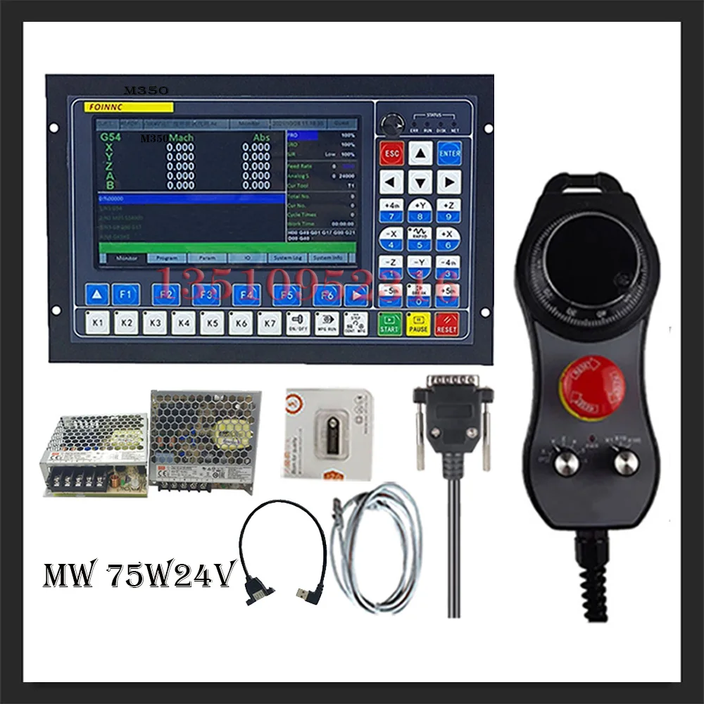
packing list: 1 x cnc controller M350 (3, 4, 5 axis optional)
1x emergency mode electronic steering wheel mpg
2x75w 24V power supply
1 x USB extension cable
1x4gb USB flash drive
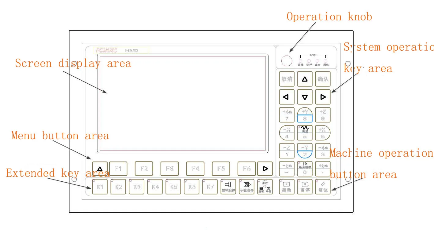
1 x network cable Introduction: The m350 system is a professional 3-5 axis motion controller based on an integrated platform. It is equipped with a 7-inch color screen, full keyboard input and customizable function keys to make the user more convenient. It supports multiple processes, straight line tool magazines, circular disk tool magazine function. The interface and structure use the conventional method on the market, with simple operation, easy to learn and understand, and convenient installation. The system uses an advanced adaptive speed control algorithm, which has the characteristics of high processing efficiency and good surface quality. Meet the needs of various engraving machines, engraving and milling machines, cutting machines. System features: Maximum number of control axes: five m350 axes, 2-5 axes linear interpolation, 2 axes arbitrary circular interpolation;
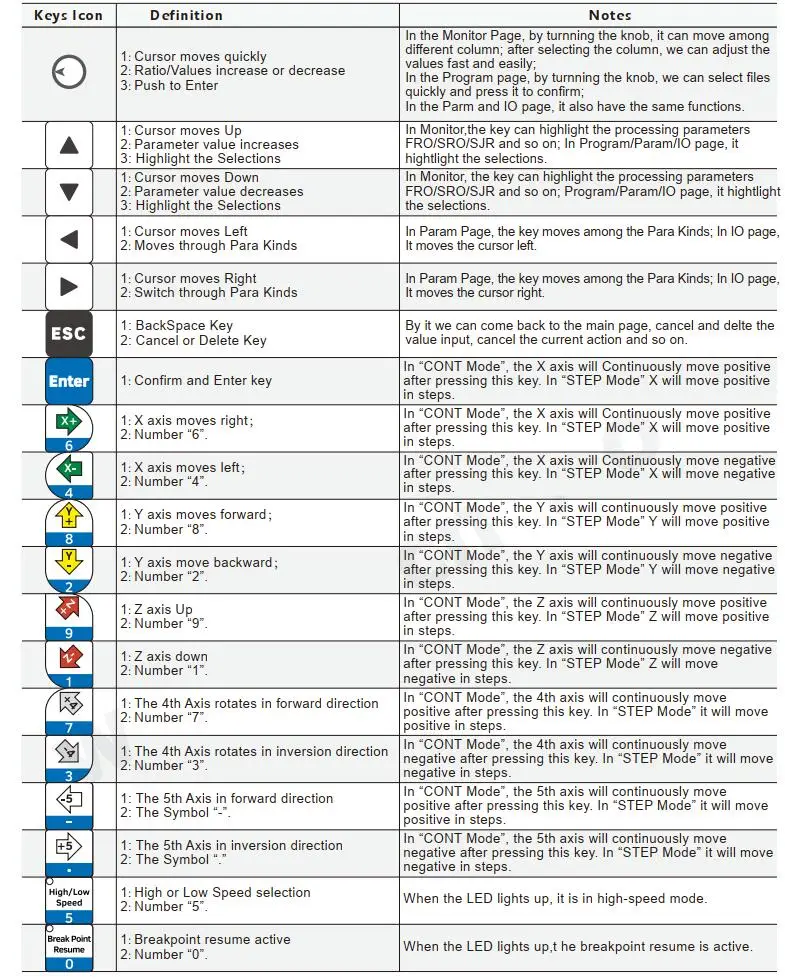
Mode of operation: conventional operation of engraving machine system;
Screen Size: 7 / 10.2 inches;
Screen resolution: 1024*600;
I/o: m6xx io 20/21 pattern, m3xx io 24/21 pattern;
Analog voltage output: 0-10v;
pwm output: only m3xxz support
Tool magazine type: multi-process, straight line, disk;
Tool setup mode: automatic and manual tool setup support;
Tool Setting Type: Fixed Tool Setting, Floating Tool Setting, First Tool Setting/Second Tool Setting;
Compensation methods: direction difference compensation, radius compensation, length compensation;
Interpolation algorithm: s-shaped, hard circular arc algorithm, soft circular arc algorithm;
Language: Chinese and English support;
cnc software alarm: program error, operation error, over-stroke error, servo drive alarm, etc.;
Network: support online file sharing and remote file processing;
Open collector output, maximum output current 500ma, can directly drive relay;
Pulse direction adopts differential output and the interpolation pulse output maximum frequency is 1mhz;
Axis control mode: multi-step speed (4 steps and 16 speeds), analog (0-10v), servo axis;
Compatible with standard g codes. General cad/cam support software like artcam, mastercam, proe.
User interacts with external file via u disk and works completely offline;
Multi-phase pre-treatment, adaptive advanced speed control of processing path, fast processing speed, high precision and good processing continuity;
High-speed continuous processing of small line segments, automatically selecting the most efficient algorithm from a variety of small line segment control algorithm;
Supports large-capacity file processing;
With breakpoint memory, auto power off protection function, near point processing function and designated line processing;
Time lock function;
Support four operation permissions (Guest, Operator, Administrator, Super Administrator);
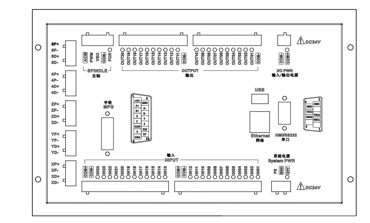
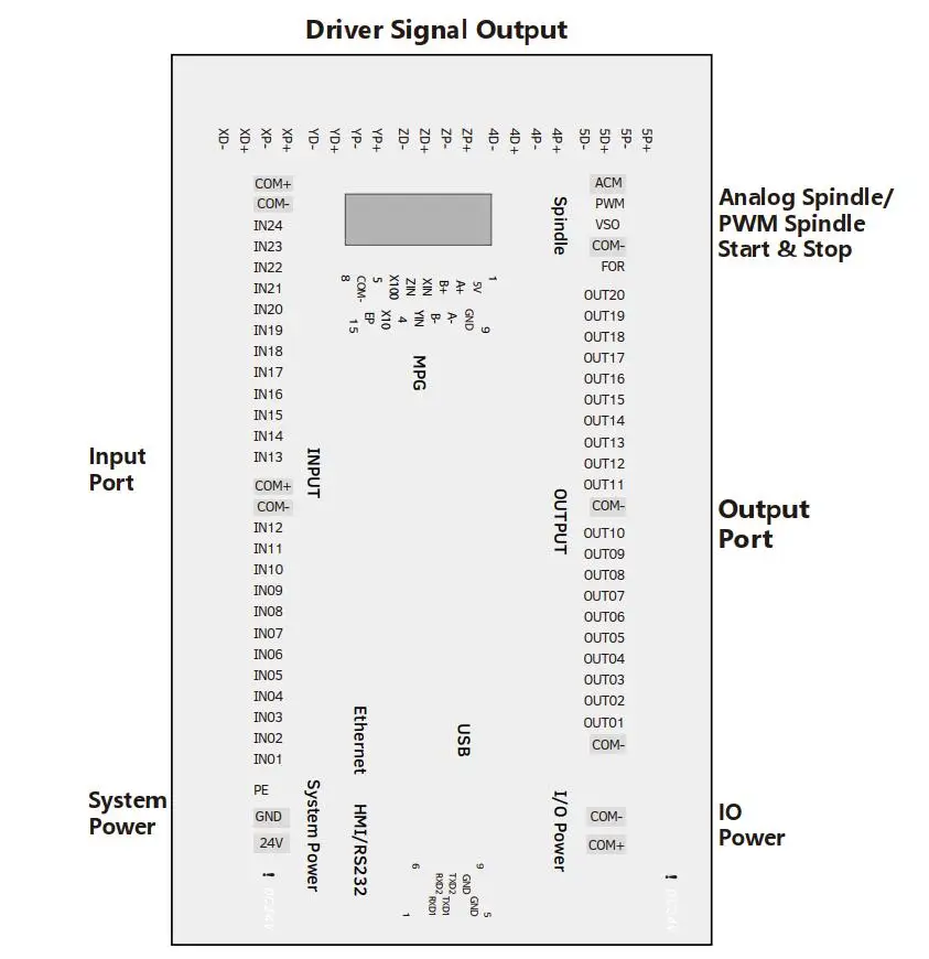
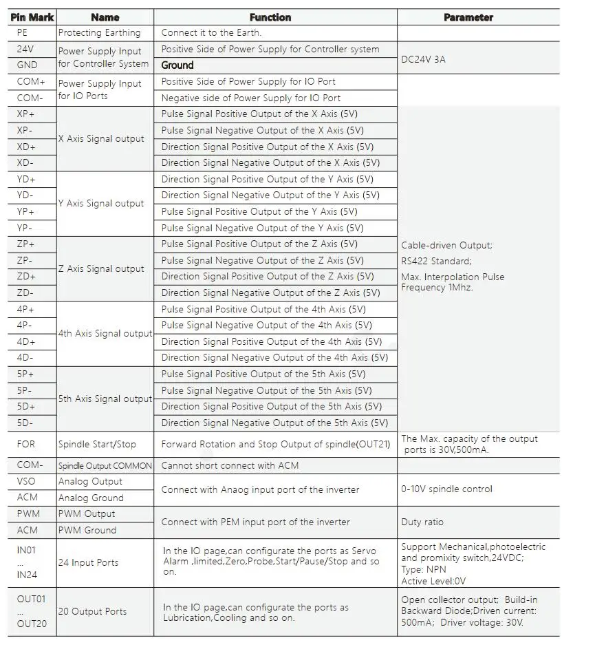
With automatic return to origin, return to reference point, workpiece origin saving and load function;   Introduction to Wiring: 1) system power supply and io power input port;
2) driver signal output port;
3) entry and exit ports;
4) shaft exit port;
5) mpg port;
6) ethernet and usb interface;
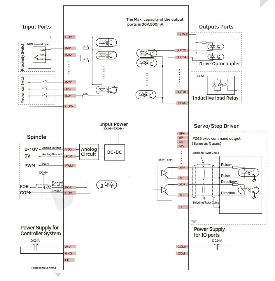
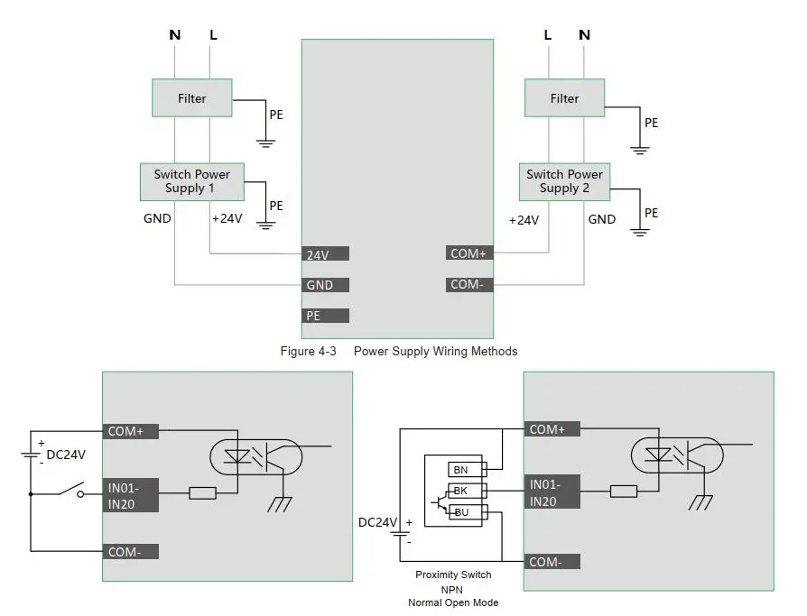
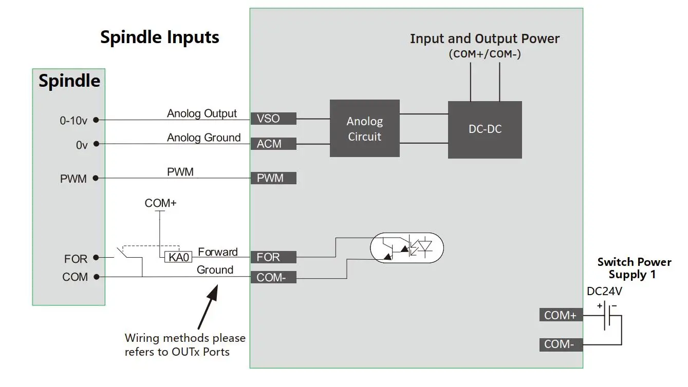
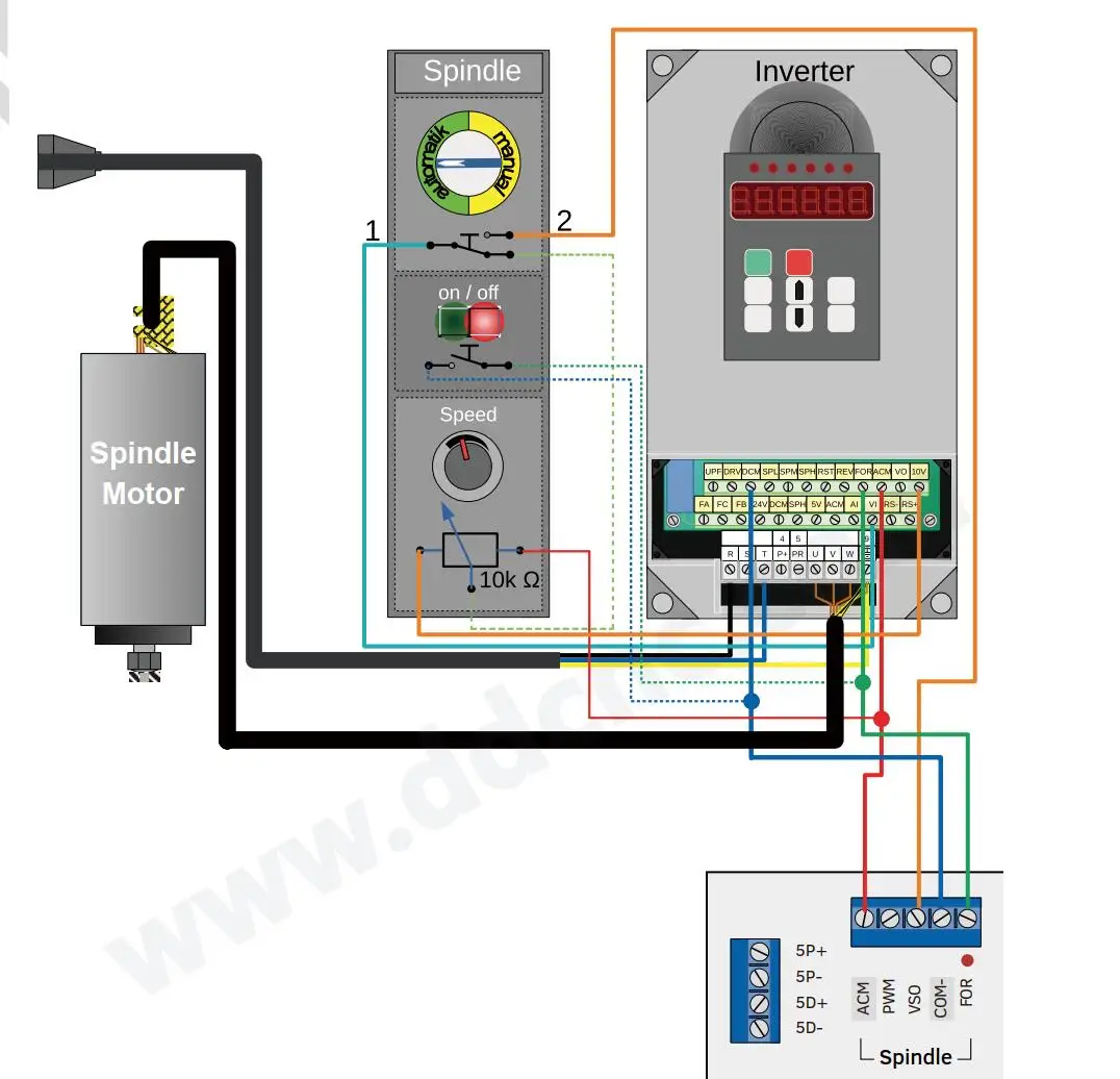
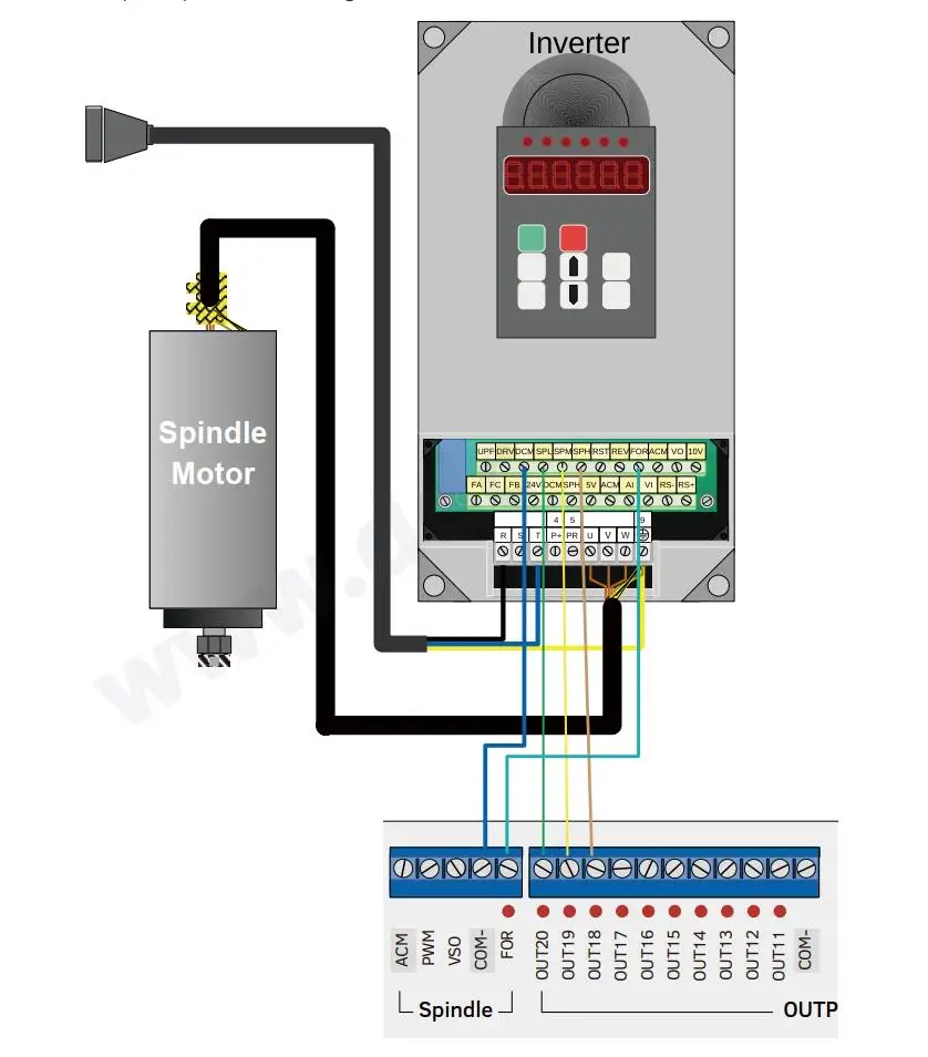
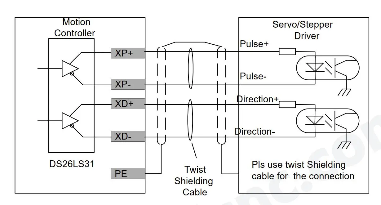
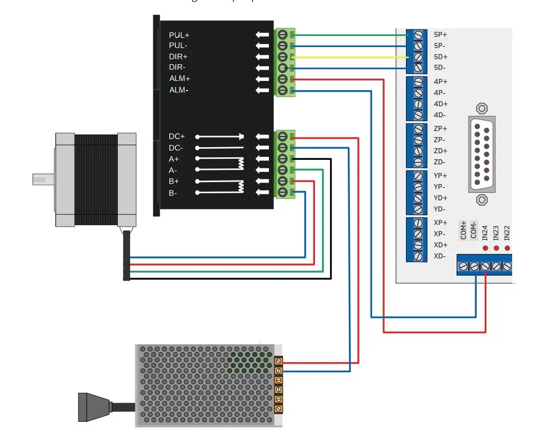
7) hmi/rs232 interface. M350 requires two power supplies, the main power supply is used for the controller system, and the io port power supply is used for input and output and the mpg port. Both power sources are 24vdc and current is 3a. The main power input port is the power input port, marked with 24v and gnd. Between the io power input ports, with + and com- are the input/output ports and the mpg power input ports. Please, keep. Remember that the controller can function normally only if the two power sources are correctly connected. Many new users only supply power to the system, and so only limited switches, relays, mpg and spindle don't work at all, so please check if it's still supplying power to the io port. The io power supply supplies power to all io ports, including restricted switches, relays, mpg, etop, and all other input and output ports. Without it, the axis, mpg, input and output ports will not work. To avoid electrical noise, it is strongly recommended to use two separate 24v power supplies. In order to avoid high frequency electrical noise from the power cord, it is strongly recommended to install a noise filter at the power input end of the switching power supply. 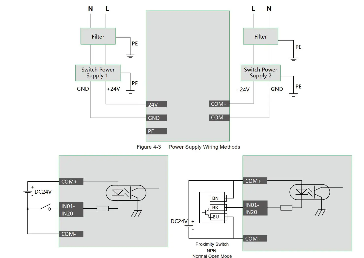 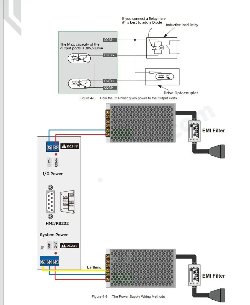 Introduction to Inverter Wiring: On the analog axis, the speed control output terminal can output 0-10v. It can be adjusted by sending a voltage between 0 to 10v to the vfd, the speed of motor shaft speed adjustment of the shaft shaft. Use vfd (variable frequency drive) to control axis speed, just need start/stop signal and 0-10v signal to control frequency. The to port wiring method is the same as the normal output port. Para is used for forward axis output or start/stop output; the analog circuit is isolated from the power output, not short circuit acm and com-(dcm); If you only need the start and stop commands of the axis, you just need to connect the output port to the controller frame with the Inverter start input port Wiring unit: Step/servo control output, we use differential pulse and direction output method
As shown in Figure 1-12. 1mhz across the shaft. There are 3 or 4 or 5 axis options.
Figure 1-12 takes the centerline of x as an example, y, z, a and b are the same wiring methods.
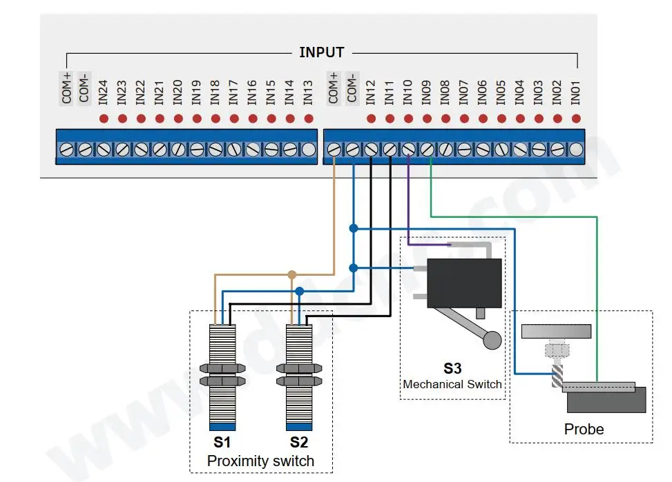
Pulse and direction signal output voltage is ±5v Wiring Input Signal: M350 input and output are user defined io ports, in our example we set in12,
In11 and in10 are used as the "centerline limit signal" input ports, and we set in09 to "probe"
Exit door.
Please note that the limit switch type must be npn normally open, and the voltage range is
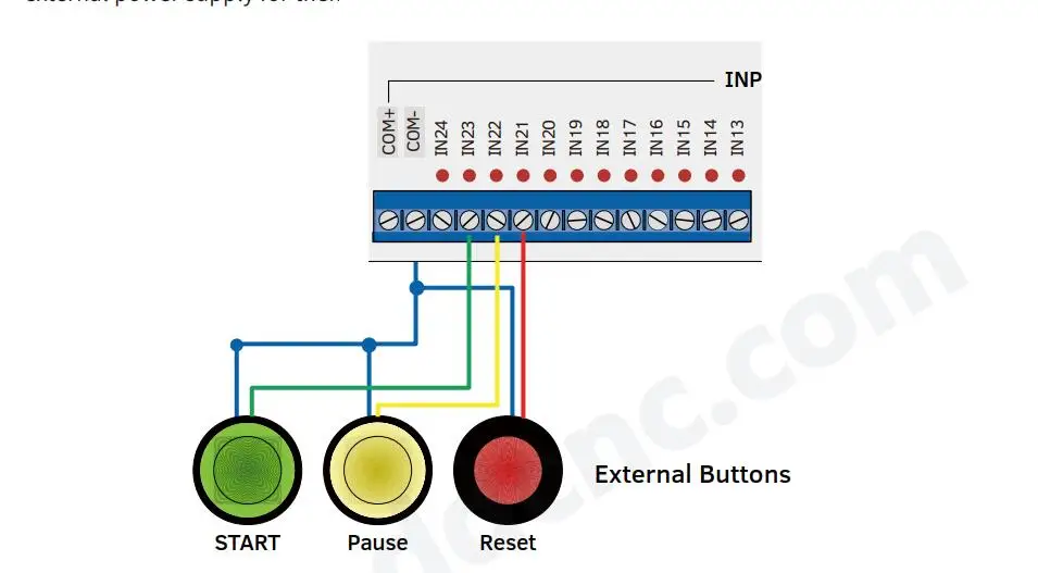
24VDC M350 input and output are user defined io ports, in our example we already set in23
As the “Start External input port”, IN22 as the “Pause” External input port, and IN21 as the “Stop External input port”.
Please choose external buttons which is 24vdc power supply input. So there's no need for a
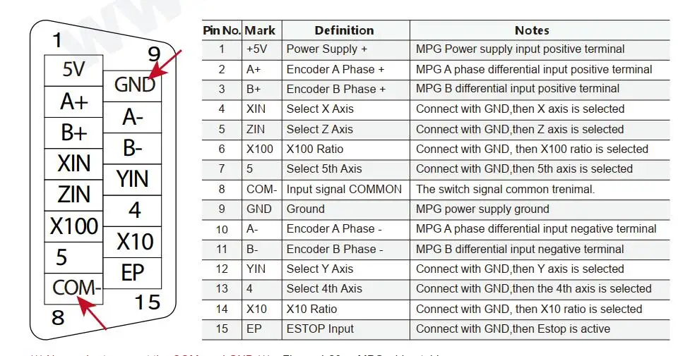
External power supply for them MPG wiring: Important:
1) the common terminal of all input signals is com- instead of gnd; do not short circuit gnd and
WITH-;
2) mpg needs to be fed through io power port (with +/com-), otherwise mpg cannot work;
3) Due to pin limitation, if x10 and x100 are not selected, the system only needs to select x1
Pattern.
4) use mpg and press "trial cut" button, system can be changed to "steering wheel guide" mode.
boot) can be active
|
|
|
|
|


 배송기간
배송기간


