APPLICATION
Multi-function time relay can be used for industrial equipment, lighting control, heating element control, motor, fan control.There are10 delay modesand itsdelay rangecovers0.1secto 10 days.
Features
-10 delay modes: -5delay modescontrolled by power
-4delay modes controlled by signals
-1pulse conversion mode
- Ultra-wide delay range, can be setfrom0.1sec-10 days (10 gears).
- Available with AC/DC 12V-240V ultra wide operating voltage.
- Relay working status is indicated by LED indicator light.
- Ultra small volume, only 18mm wide,35mm rail installation.
Model and Meaning
Rated working supply voltage:
A220:AC220V
W240:AC/DC12V-240V
Output contact groups
1:1Z
2:2Z
Technical data
Item No. |
TBT7-A1 |
TBT7-A2 |
Function |
A,B,C,D,E,F,G,H,I,J |
Supply terminal |
A1-A2 |
Rated control supply voltage |
AC/DC 12-240V(50-60Hz) |
Consumed power |
AC0.09-3VA/DC 0.05-1.7W |
Rated control supply voltage |
AC 220V(50-60Hz) |
Consumed power |
AC max.6VA/1.3W AC max.6VA/1.9w |
Allowable power supply fluctuation range |
-15%;+10% |
Power indicator light |
Green LED |
Delay range |
0.1sec-10 days, NO, NC |
Setting mode |
Knob |
Setting precision |
10% |
Repeat precision |
0.2% |
Temperature fluctuation error |
0.05%/℃,at=20℃(0.05%℉,at=68℉) |
Output contact parameter |
1 set of conversion contacts 2 sets of conversion contacts |
|
16A/AC1 |
|
250VAC/24VDC |
Min transfer power |
500mW |
Output relay indication |
Red LED |
Mechanical life |
1×10⁷ |
|
Electrical life (resistive load) |
1×10⁵ |
Reset time |
Max. 200ms |
Working ambient temperature |
-20℃~+55℃ |
Storage and transport ambienttemperature |
-35℃~+75℃ |
Installation mode |
35mm railinstallation |
Protection level |
IP20 |
Installation position |
Any |
Installation altitude height |
≤2000m |
Pollution level |
2 |
Wiring capacity |
1×2.5mm2or2×1.5mm2 |
Outline size |
90mm×18mm×64mm |
Weight |
W240-62g,A230-60g W240-82g,A230-81g |
Compliant standard |
GB14048.5,IEC60947-5-1,EN 61812-1 |
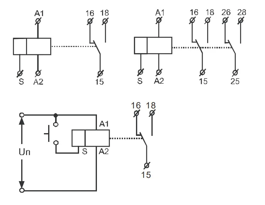
Wiring
diagram
As shown in the figure, the load (such as contactor, indicator light, electromagnetic relay, etc.) can be connected in S-A2.The load is energized when S is closed.
Functional diagram
A: Power-ondelay
When the relay Un gets power, the relay starts to delay, and the output contact closes after delay t.After the relay Un is disconnected, the output contact is disconnected, and the S control signal is invalid in this functional mode.

B:
Power-off delay
When the relay Un gets power, the output contact of the electric appliance will close immediately and start delay. After delay t, the output contact will be disconnected. If the delay timetfails to reach the relay Un and loses power, the output contact will be disconnected and thecontrol signal of S will be invalid in this functional mode.

C: Cycle delay (OFFstart)
When the relay Un getspower, the relay starts to delay.The output contact is closed after delay t.At the same time, after the delay time t, theoutputcontact of the relay will be disconnected. In this way, the delay time will continue until the relay Un loses power, and the control signal of S will be invalid in this functional mode.

D: Cycle delay (start ON)
When the relay Un gets power, the relay closes and starts to delay. After delay t, the output contact is disconnected, and at the same time, the output contact of the relay is closed after delay time T. In such a cyclic delay, until the relay Un loses power, thecontrol signal of S is invalid in this functional mode.

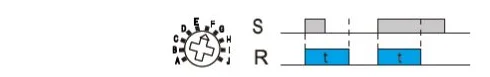
E:Power-off delay(S falling edgetrigger start)
When the relay Un is in the state of power on, when thecontrol end of S is switched on, when the relay is closed, the relay starts to delay when the system end is disconnected. After the delay t, the output contact is disconnected. In the process of delayt, the control end of S is reconnected, and the delay T is reset and delayed again.

F:Power-off delay(S rising edge trigger start)
When the relay Un is in the state of power on, when thecontrol end of S is switched on, the relay closes, and the relay starts to delay at the same time. After delay T, the output contact is disconnected. In the process of delay T, the control end of S is reconnected, while the delay t remains unchanged and continues to delay.
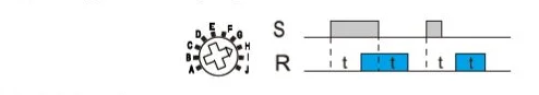
G: S falling edge triggers closes, andpower-off delay
When the relay Un is in the state of power on, when thecontrol end of S is disconnected, the relay closes, and at the same time, the relay starts to delay. After delayt, the output contact is disconnected. In the process of delay T, the control end of S is reconnected and disconnected, while the delay t remains unchanged and continues to delay.

H:Power-On/off delay
When relay Un is in power on state, when S control end is switched on, the relay starts to delay, and the output contact is closed after delay T; when S control end is disconnected, the relay starts to delay, and the output contact is disconnected after delay T.
I: Pulse conversion
When the relay Un is in the electrified state, when thecontrol end of S is switched on, the state transition of relay output contact is achieved.

J: Pulse output
When the relay Un gets power, the relay starts to delay. When the delay timetarrives, the relay output contact closes for 0.5s and then disconnects.

Time Range
0.1-1s |
1-10s |
6-60s |
1-10m |
6-60m |
1-10hr |
0.1-1day |
1-10day |
only on |
only off |


 배송기간
배송기간


