


 aHR0cDovL2ZyZWVzaGlwLmNvLmty
- 브랜드 이름: Dykbcells
- 근원: CN (정품)
- DIY 용품: 전기
- 크기: Digital LED 10A high power
- 작풍: electronic switch speed control
- 출력 유형: dimming Motor module
- transistor PWM regulation: Digital LED 10A high power
- dimming Motor module: MOS tube field effect
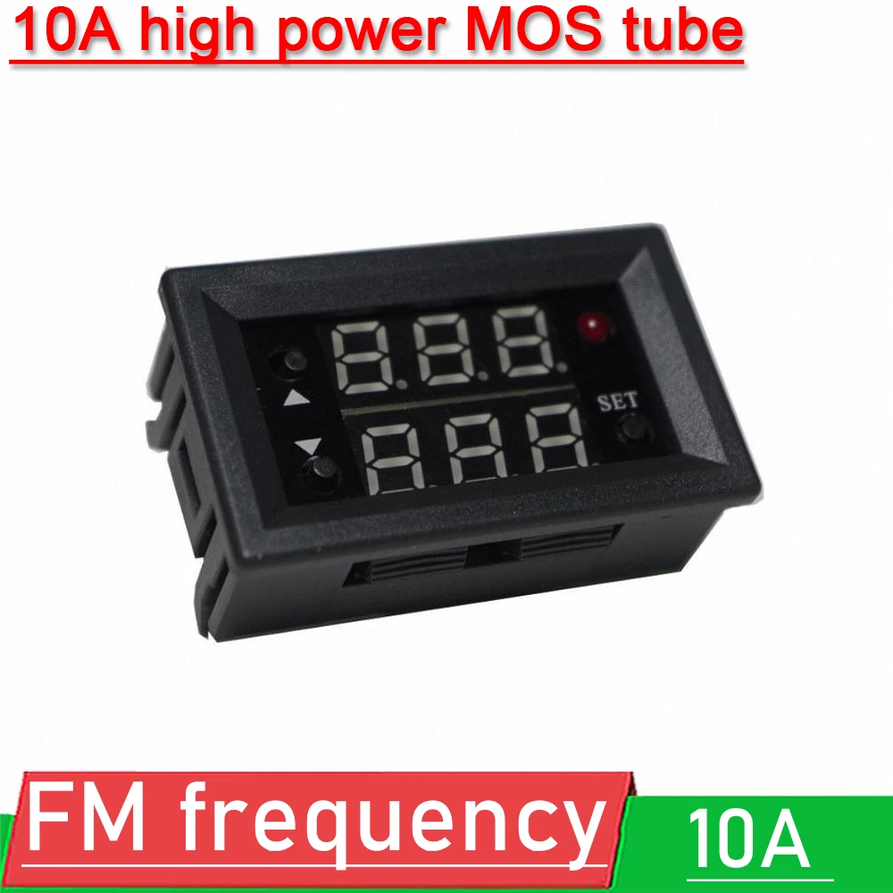
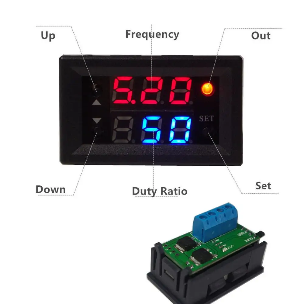
Digital display 10A high power MOS tube FET PWM adjustment electronic switch FM frequency dimming module
Features:
PWM high power switch
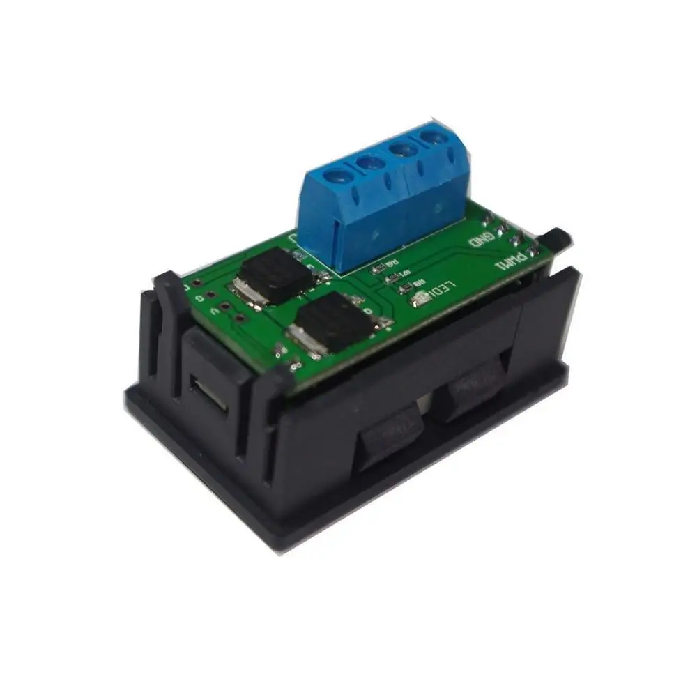
SIZE : 45.2MM*25.8MM*15MM
Frequency range : 1HZ-160KHZ
Duty cycle : 0-100%
Frequency accuracy : 2%
Signal load capacity : Output current 10A
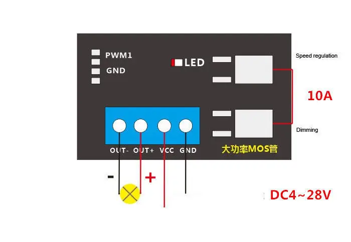
Digital display PWM high power switch, frequency and duty cycle are independently adjustable. The module integrates dual MOS tube circuit, the load current is 10A at normal temperature, and the maximum can be up to 15A under auxiliary heat dissipation. The output can directly drive high-power equipment such as motor, bulb and solenoid valve. The output voltage is equal to the input voltage, and the wide voltage input (DC 4~28v) can meet the needs of different users.
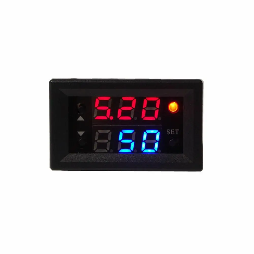
Frequency and duty cycle setup process:
The frequency is divided into four ranges and automatically switched:
1.XXX (no decimal point): value 1Hz~999Hz, unit 1Hz
2.X.XX (the decimal point is in the hundred digits): the value is 1.00KHz~9.99KHz, the unit is 0.01KHz
3.XX.X (decimal point is ten): value 10.0KHz~99.9KHz, unit 0.1KHz
4.X.X.X. (full decimal point): value 100KHz~160KHz, unit 1KHz
E.g:
100 means 100Hz
1.00 means 1.00KHz
10.0 means 10KHz
1.0.0. means 100Khz
Duty cycle 0~100% adjustable
Setup process:
1. Press the SET button, the frequency parameter flashes, and the frequency is set by the UP or DOWN button.
2. Press the SET button, the duty cycle parameter flashes, and the duty cycle is set by the UP or DOWN button.
3. Press the SET button to exit the setting.
4. Press and hold the UP button and DOWN button to increase or decrease quickly.
5. Data is automatically remembered, and all setting parameters are saved after power down.
1. Used as a square wave signal generator to generate square wave signals for development and use.
2. Used to generate a square wave signal that drives a stepper motor driver.
3. Generate adjustable pulses for use by the MCU.
4 Generate adjustable pulses to control the associated circuitry.


 배송기간
배송기간


