|
|
     aHR0cDovL2ZyZWVzaGlwLmNvLmty aHR0cDovL2ZyZWVzaGlwLmNvLmty
- 스마트 기기: no
- 신청: 선반 터닝 센터
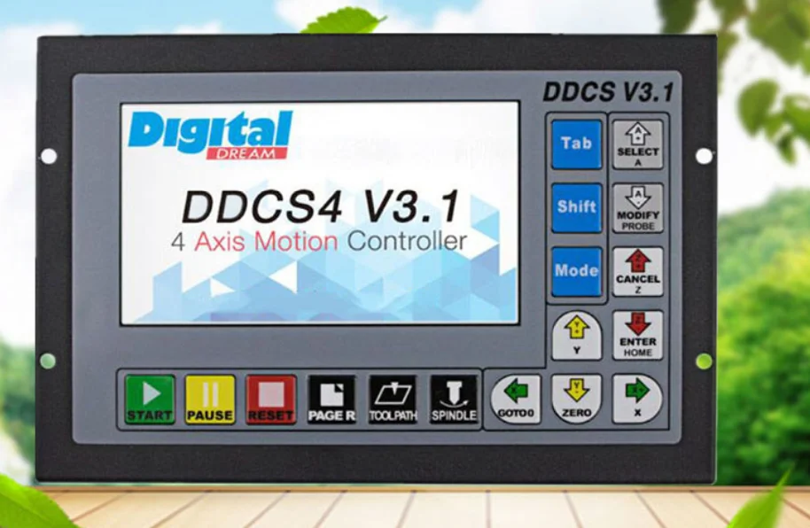
- 모델 번호: DDCS V3.1
- 근원: CN (정품)
- 증명서: 세륨,ROHS
Product packaging: 1 x DDCSV3.1 CNC offline controller (3/4 axis optional)
1 x Electronic handwheel with emergency stop
1 x 4GB USB flash drive
1 x USB extension cable accessory
1 mounting bracket
1 steering wheel hook
1 x 3D Touch Probe Edge Finder Performance parameter of the DDCS V3.1 1) 16 opto isolated digital inputs,3 opto isolated digital outputs;
2) Upgrade algorithm,support soft interpolation,fixed arc interpolation bug of the old version;
3) Analog spindle control 0-10V spindle control (can be modified as PWM output);
4) 3-4 axis motor Control.Differential Pulse and direction output signal,Max.500Khz per axis;
5) ARM9 main control chip,FPGA core algorithm chip;
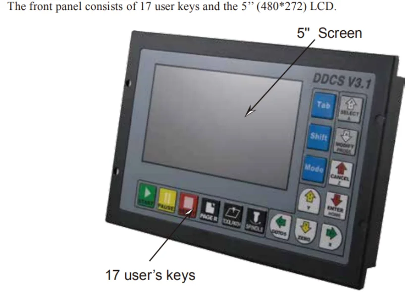
6) 5 inches TFT screen, resolution ratio: 480x272,17 operation keys;
7) 24VDC power input, minimum Current is 0.5A;
8) USB flash disk support for G code file input,no size limited of the G-code file;
9) 1GB internal memory;10) Support standard MPG;
11) Jog function for each axis (continuous, step, defined distance);
12) Support the operation of quickly specify the running position;
13) Support for “Power Cut” recovery. Data is automatically saved;
14) Support the origin and Limit share the same Input ports;
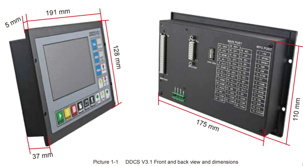
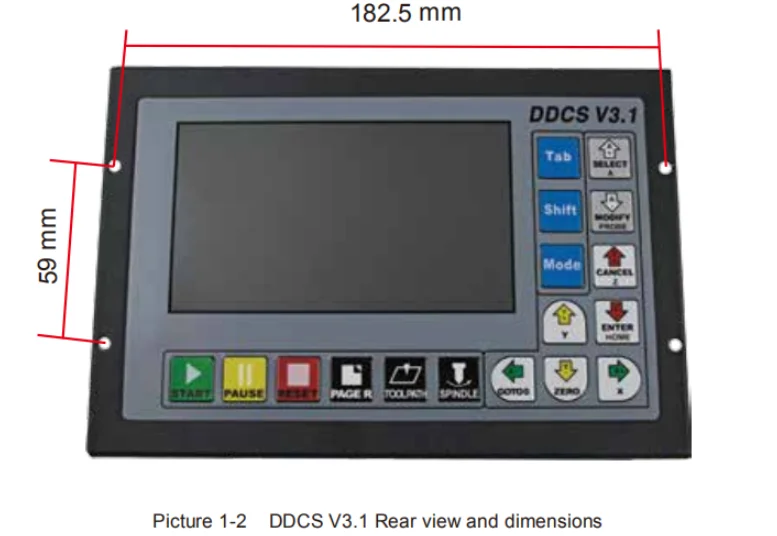
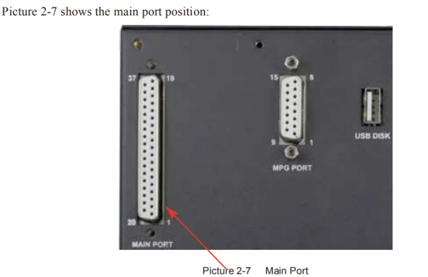
15) The controller only support NPN type limited switch. DDCS V3.1 Appearance and Size At the back side of the controller,there are USB Disk interface,MPG Port,Main Port and external
Start/Pause/Estop interface.
In order to make convenient for the connection,we also apply the 3 layers wiring terminal for main port.
We also supply a DB-15 Ma plug for MPG connection.
The 8 screws are to fix the wiring ternimal and controller.
The U-disk is for the transfer of the G-code file. 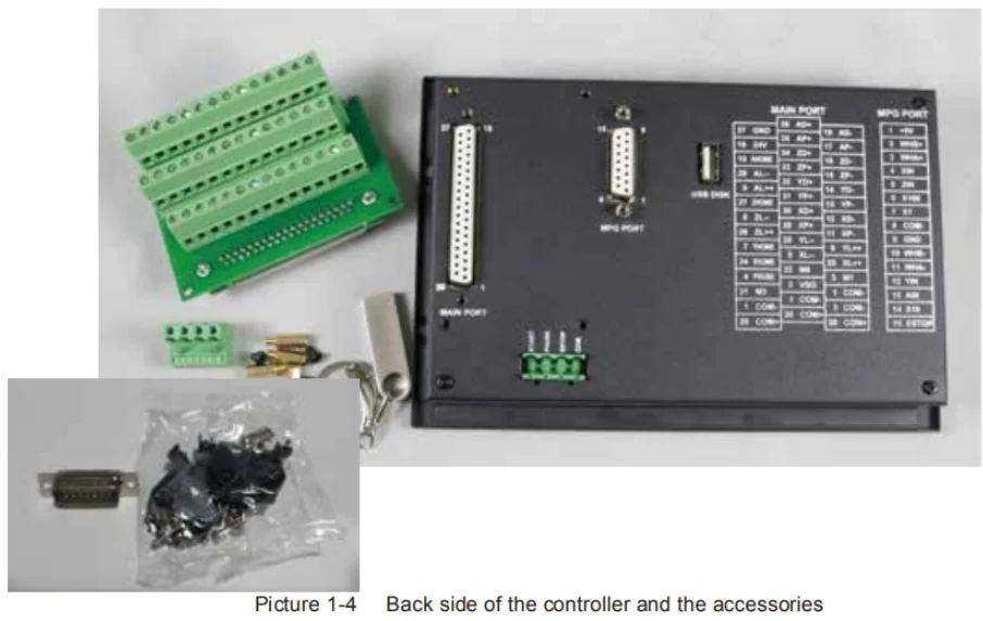 Explanation of Abbreviations When operating the DDCS, the users will come across some English abbreviations. Here a list with expla�nations.
FRO: Feed Rate Override
SRO: Spindle Rate Override
SRJ: Jog Speed Setting
F: Feed rate, unit is mm/min
S: Spindle Speed, unit rev/min.
X: The coordinate code of the X axis.
Y: The coordinate code of the Y axis.
Z: The coordinate code of the Z axis.
A: The coordinate code of the A axis
BUSY: The system is busy. You still can adjust
FRO and SRO
READY: READY mode, any operation can be done
RESET: Reset mode, controller is in “OFF” mode, no operation can be performed
CONT: Continuous mode, each axis can be manually jogged with the arrow keys
Step :Manual Step Mode,each axis can be jogged in defined steps
MPG: MPG mode. Operate the machine with the MPG (Manual Pulse Generator)
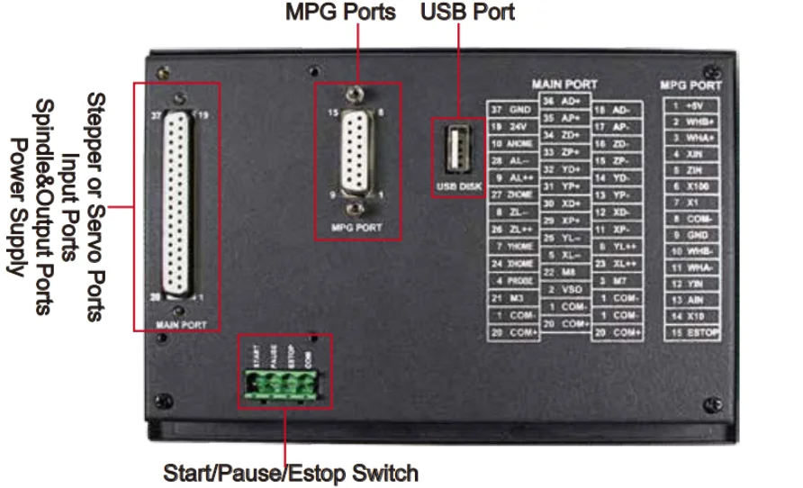
AUTO: Run G code. Auto is showing when file is processing As the picture shows, the wiring section of the controller has Input Ports,Spindle&Output
Ports,tepper/Ser�vo control step and direction
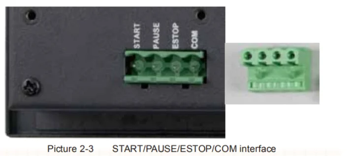
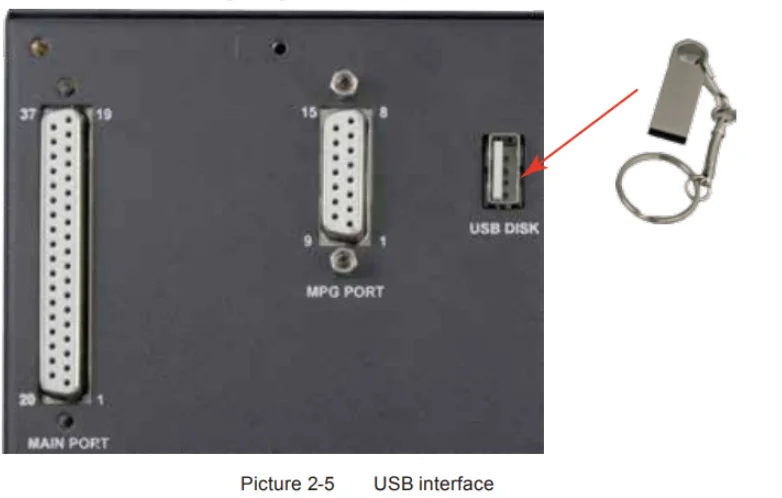
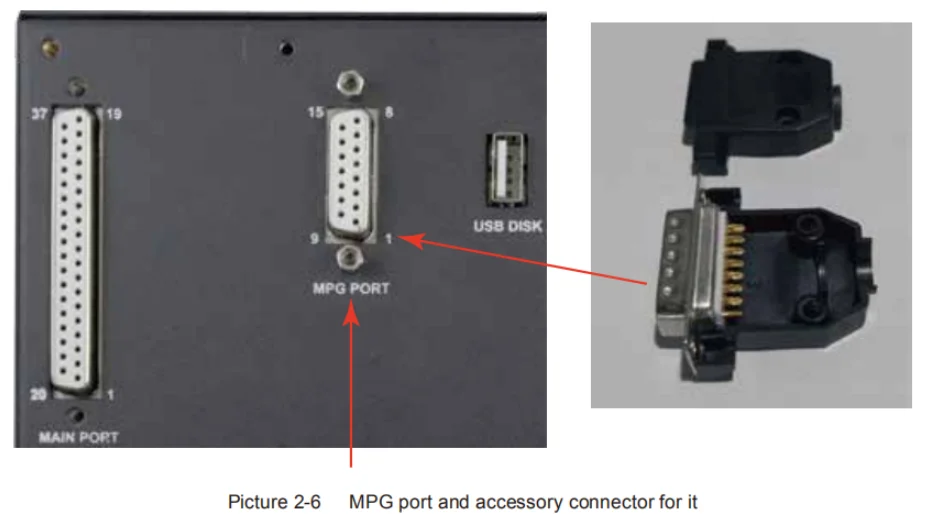
output,MPG Port, USB Port and Power supply Port. START/PAUSE/ESTOP Switch Wiring As Picture 2-3 shows, the power interface,there is a screw termimal for connection. The marks are the “START”/”PAUSE”/”ESTOP” and “COM” for external switches. And Picture 2-4 is the circuit drawing for the connection. USB Wiring This USB port is the standard USB A-type. A 50cm USB extension cord with installation plug is supplied with the controller. See sketch diagram picture 2-5 for reference. MPG Port The MPG port is shown in Picture 2-6. It is the DB15 Female terminals next to the USB port.
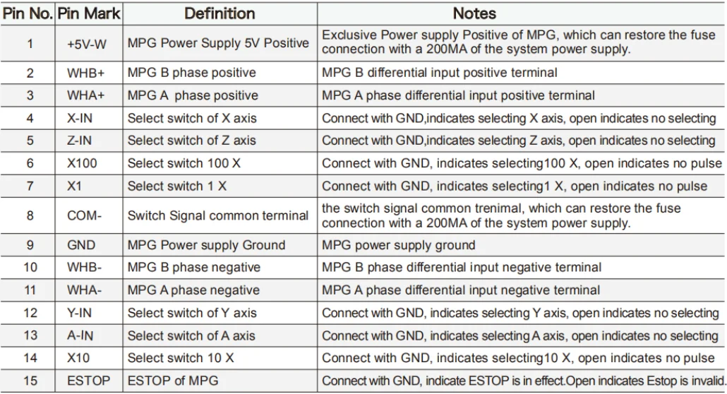
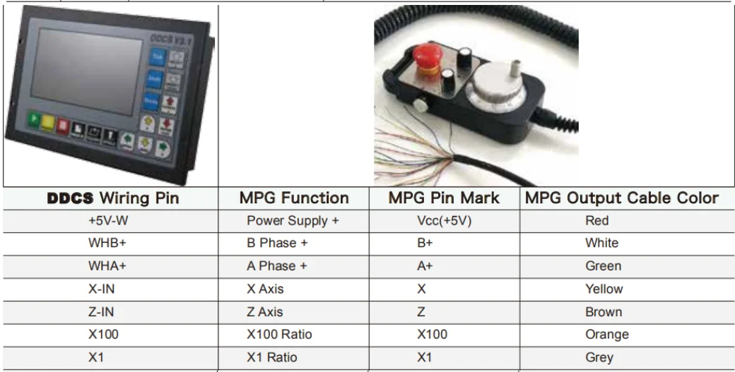
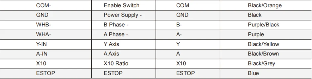
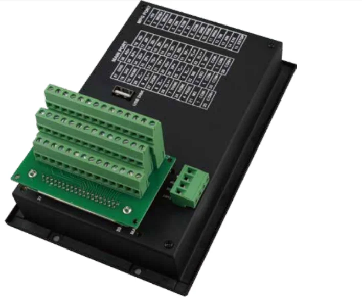
The users need to weld the MPG cables into the DB15 Male terminal,and plug-in to the MPG port of the controller MPG port. The MPG port has 15 pins, see Table 2-1 for reference. See Table 2-2 and table 2-3 for the wiring. We also supply a wiring terminal to fit the 37 female pins,which make the convenient for the wiring.Pls note the following photo.At the termimal 4 conners,there are screws to make the terminal locked-onto the controller. There are 3 layers of the Wiring Terminal.Pls note the following photo,which showed the pin No.s and Pin
Mark and definition.It include:
1) Stepper/Servo Output Ports;
2) The Spindle Control Output Ports;
3) The E-stop,Limit,Home and Probe and other Inputs ports;
4) 24V DC Power Supply ports for the Controller;
5) 24V DC Power Supply ports for the I/O Unit. 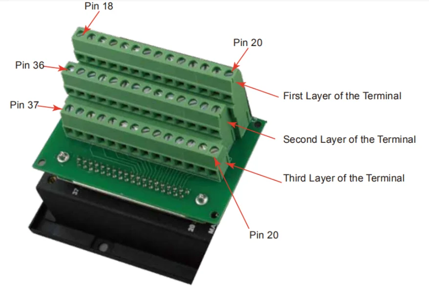 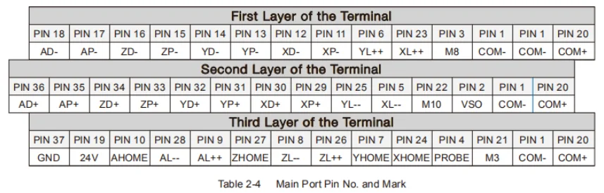 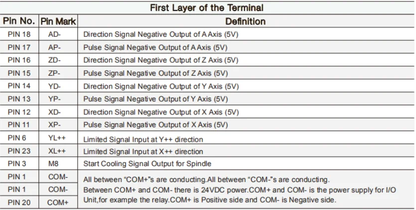 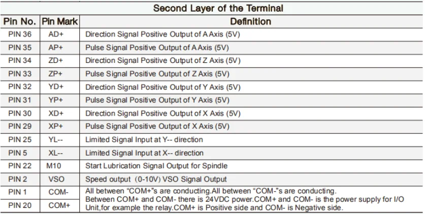 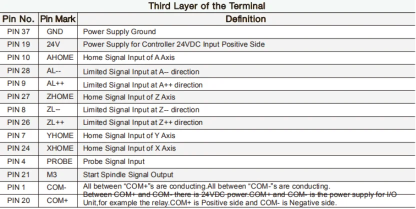 3D Touch Probe, by connecting CNC (Mach3, GRBL control board)
Signal input port (for knife edge) to realize fast centering, edge finding, circle center finding, table shape measurement, etc.
Greatly solves the trouble of positioning the workpiece for secondary clamping during the processing.
Working voltage: DC 5 - 24V wide voltage
Indicator light: green light when power on, red light after triggering
The shell is made of fine matte black + silver oxidized aluminum alloy, with a flat anti-roll design, and the stylus is stainless steel.
Machined, the ball head is wear-resistant with tungsten steel balls.
Compatible with various control boards/boxes such as grbl control board and Mach3 1. Do you need to open the spindle speed? Never, never, never.
2. How to distinguish the three lines? The red wire is VCC, the black wire is GND, and the white wire is IO.
3. Why is the concentricity different every time the probe is installed?
Because your ER collet spring clip can't guarantee 100% positive position. After each installation of the probe, even if the concentricity is adjusted to 1 wire, there will still be deviations when the probe is removed and installed again. Therefore, it is best for your chuck to buy AAA and above precision (concentricity <= 0.005), because many domestic chucks have false marks, it is recommended to use a high-precision gauge or tungsten steel rod to check the meter after installing the chuck. Look at concentricity. The position of the lever dial indicator is preferably 50mm away from the chuck, which is probably the distance from the ball head of our probe to the root of the shank.
4. Why is the concentricity still poor even though it is an AAA chuck?
That's because, you bought the virtual standard chuck.
Under normal circumstances, if the spindle runs out by 0.01, the AAA chuck clamps the milling cutter, and the tool holder is punched, the error may not exceed 0.02, and at most 0.03. The central axis of the collet and the central axis of the spindle will have a slight angular deviation, which will be magnified by the length of your tool holder. Usually you use the calibration table to measure the root of the milling cutter, and you can't see a big error, but because the stylus of the probe is about 50mm away from the tool handle, the error will be further amplified. Therefore, be sure to choose a genuine high-precision chuck, which is nothing more than a price difference of tens of yuan. If you want to do a good job, you must first sharpen your tool.
|
|
|
|
|


 배송기간
배송기간


